looks like pot connection wrong.
simple but ifconnection 1-2-3, 1, ground, 2 amp. input. , 3input (dac)
That's the way I connected it. Put song on pause. Low volume - no noise. High volume- very small noise. In the middle it is very noticeable.
I guess I miss ground somewhere.
I used ground of pot as L12-2 input ground.I guess I miss ground somewhere.
@ OldDIY sorry if my question is supid but what transistors you use in repeater and what means 4,7MK for capacitor ?
Between the pot and the amp, I have an OP, currently a Muses 8920 that I will replace with an OPA1692, there is no hum or noise and this with my ear near to the AMT tweeters.
Idem with my DCB1 preamp.
Idem with my DCB1 preamp.
@ denbret - great, could you provide a schematics how had you connected it ?
@oldDIY - thanks but is that repeater feed by voltage from R3 side ? if so what value
@oldDIY - thanks but is that repeater feed by voltage from R3 side ? if so what value
Try with another source. I know the Allo Boss DAC is reliable, but just to make sure it's OK.
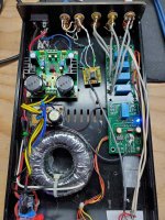
Found my problem. I didn't connect power ground to chassis. After connecting it -noise gone. Very nice and quite. Sounds better and better.

Found my problem. I didn't connect power ground to chassis. After connecting it -noise gone. Very nice and quite. Sounds better and better.
View attachment 937397
That's great. A problem solved.
@peterpl I don't have a graph for the connection, I'm coming back.
Attachments
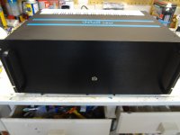
L12-2 Power Amp boards
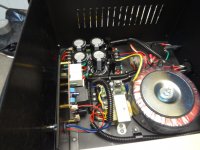
I ordered a couple of these boards to use in my project that I am currently working on. The power supply uses a 300VA Hammond Toroid and is putting out 45 volts -+.I was not too sure about these boards but glad that they seem to be good for the price. I have included a couple of pics of the amp so far. The top has been sent for a redo of the white strip on the back area
Cheers Wayne
Attachments
I used PREAMP 7 P7 MINI preamplifier. It makes mid and high frequencies more clear. It uses NJM4580 chip with very simple circuit, you can build yourself. Also, it have volume control. Perhaps, you will want to drop gain of circuit, changing 2k2 resistor with higher value . I haven't test changing resistor. now, it's very loud.
@ mdardeniz is it possible to use P7MINI without potentiometer as stage between amplifier's potentiometer and power amplifier ?
I think you can use together. Perhaps, you can adjust pre's pot and stay it fixed. I tried only with pre's pot. But, I didn't fix it in the box. I've still testting. Or, yes you can try bypass pre's pot. P7 is very simple preamplifier.
Hi,
I am using this OP socket. The advantage is that we can put the OP we like. I put an OPA1692, the sound is excellent, a lot of extension in the low and high, hyper realistic soundstage and good depth.
Dual OP Amp Preamp DC Amplification Empty Board for NE5532/OPA2134/OPA2604/AD826 | eBay
I am using this OP socket. The advantage is that we can put the OP we like. I put an OPA1692, the sound is excellent, a lot of extension in the low and high, hyper realistic soundstage and good depth.
Dual OP Amp Preamp DC Amplification Empty Board for NE5532/OPA2134/OPA2604/AD826 | eBay
Hi guys,
Let me ad my 2 cents to this fine conversation.
I have purchased a DIY set and have measured all components before soldering. I have a Ver. 4 board. Everything was okay. All components have proven to be just fine.
I have made measurements of this board fed from capacitance multiplier at 22 and 42 rails.
For load I have used three 22R/100W resistors (Arcol HS100 22R J) in parallel.
I have warmed up the amplifier for 1 hour before taking measurements.
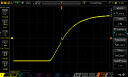
Everything was just fine except a small detail shown on the snapshot below. The figure shows magnified initial part of response to square wave at 1KHz. Similar response can be detected at both 10Hz and 20KHz. However, at 42V rails this distorted response vanishes completely and the square wave response at 1kHz is perfect.
This indicates to me that this board was designed to run at 40-50 V rails. Also, there was no need to meddle with bias and DC drift. The both boards have consistent values without any modification whatsoever. I have decided to leave the boards without any attempt for improvements because I believe LJM knows exactly what's he doing.
Let me ad my 2 cents to this fine conversation.
I have purchased a DIY set and have measured all components before soldering. I have a Ver. 4 board. Everything was okay. All components have proven to be just fine.
I have made measurements of this board fed from capacitance multiplier at 22 and 42 rails.
For load I have used three 22R/100W resistors (Arcol HS100 22R J) in parallel.
I have warmed up the amplifier for 1 hour before taking measurements.
Everything was just fine except a small detail shown on the snapshot below. The figure shows magnified initial part of response to square wave at 1KHz. Similar response can be detected at both 10Hz and 20KHz. However, at 42V rails this distorted response vanishes completely and the square wave response at 1kHz is perfect.
This indicates to me that this board was designed to run at 40-50 V rails. Also, there was no need to meddle with bias and DC drift. The both boards have consistent values without any modification whatsoever. I have decided to leave the boards without any attempt for improvements because I believe LJM knows exactly what's he doing.
Attachments
What is first voltage, when square wave distorted? I'm using 2x20ac and about 2x31v dc.Hi guys,
Everything was just fine except a small detail shown on the snapshot below. The figure shows magnified initial part of response to square wave at 1KHz. Similar response can be detected at both 10Hz and 20KHz. However, at 42V rails this distorted response vanishes completely and the square wave response at 1kHz is perfect.
Hello mdardeniz,
Unfortunately, I cannot answer this question because I couldn't change the voltage continously - that is the nature of capacitance multiplier. There is no regulation but efficient removal of ripple.
However, there is a good news: (1) that distortion is so small that I had to magnify it by stretching the time scale. (2) you are at higher voltage and it wouldn't be audible. Sine wave response is really 'blameless'.
I have presented that result to indicate that the amplifier itself was designed for the use at higher voltages.
Regards 🙂
- Home
- Amplifiers
- Solid State
- L12-2 CFP Output amp 120W*2 8R