@denbret: Do you know the differences between various versions of the PCB?
No, I don't know the different ones. As the discussions progressed, I know Ljm recommended removing a capacitor in a specific location, then I imagine he made small adjustments.
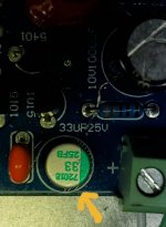
I received my parts for the bypass on the condos as proposed by Calvin's. Also I received Elna Silmic II 33uf 25v to replace the signal input one. I put a photo with the value on the pcb.
Attachments
I believe there is no two different L12-2 circuit. Only we can adjust bias current and L12 behave like class A amplifier. If you adjust as 40ma or low it's class AB.
This bias current is over the current on R13&R20. You can adjust with changing value of R19. So, idle current of L12 must be less than 40ma or like that.
You said a capacitor removed; This cap. was in the early versions. It changes the bandwidth of L12, it's not related with any current of L12.
This bias current is over the current on R13&R20. You can adjust with changing value of R19. So, idle current of L12 must be less than 40ma or like that.
You said a capacitor removed; This cap. was in the early versions. It changes the bandwidth of L12, it's not related with any current of L12.
Yes I agree, removing the capacitor has no relation to the bias current. Also there must be only one version, the change of resistance changes class A or AB
Attachments
Last edited:
I believe there is no two different L12-2 circuit. Only we can adjust bias current and L12 behave like class A amplifier. If you adjust as 40ma or low it's class AB.
This bias current is over the current on R13&R20. You can adjust with changing value of R19. So, idle current of L12 must be less than 40ma or like that. .
My board has 1k for R19. What should it be for a lower bias current/Class-AB?
My board has 1k for R19. What should it be for a lower bias current/Class-AB?
To answer my own question: I had to increase R19 to ~1.2k in order to lower idle power consumption to ~15w per channel.
.. and the protection board tripping seems to be an unrelated issue.
Last edited:
(snip)
From first glance on the PCB I missed a Bias pot and indeed this is a tweak one should perform, since the Bias may vary wildly from module to module.
A 1k8 resistor, paralled with a 10k Pot (I always use 12- or 23turn types, e.g type 64W) instead of the 1k R19 allows to trim the Bias to the desired value.
(from Calvin's post #32, about the bias)
You said a capacitor removed; This cap. was in the early versions. It changes the bandwidth of L12, it's not related with any current of L12.
I didn't assume that.
15W not looks like good for idle amplificator. R13 current must be more than 500ma ?? Am I wrong?
you have to read around 100mv on r13. Measure voltage on r13, don't measure from other place.
you have to read around 100mv on r13. Measure voltage on r13, don't measure from other place.
15W not looks like good for idle amplificator. R13 current must be more than 500ma ?? Am I wrong?
you have to read around 100mv on r13. Measure voltage on r13, don't measure from other place.
R13/R20 quiescent current for mine is about 250mA, so that the amplifier will operate in Class-A mode for the first several watts (10W or so).
I will play with the idle current after fixing my speaker protection timing issue.
R13/R20 quiescent current for mine is about 250mA, so that the amplifier will operate in Class-A mode for the first several watts (10W or so).
I will play with the idle current after fixing my speaker protection timing issue.
If so, you are not using 1k constant r19? With 1k- R19&R10 gives less than 15ma idle current (not theoretically, measured). I have changed R19 with trimpot and I'm using 10ma idle current (0.1 ohm R20,R13 and 1mv over them). note that I tried 50+ma idle current, I didn't hear any change in sound. Only output transistors warm up 🙂
R13/R20 quiescent current for mine is about 250mA, so that the amplifier will operate in Class-A mode for the first several watts (10W or so).
I will play with the idle current after fixing my speaker protection timing issue.
Remember that this has CFP output. If you increase the bias, technically you increase switching distortion. If you reduce the bias, well, you have another distortion 🙂 A big dilemma.
But in my observation, those who have sensitive hearing or very experienced with audio tend to prefer lower bias (And so it seems with the designer of this L12 amp).
Rod Elliot has CFP output amp, the P3A (class-B) and P3B (class-A) and he didn't think P3B is better than the P3A.
With your high bias current, try trimming the bias (must have a trimmer) while listening to the best bass sound you are familiar with. Everyone can perceive bass quality well. Expect better bass with lower bias.
My approach to the CFP design is to understand that the amp should be biased quite low, then try MY BEST to address the weaknesses of class-B amps (especially fatigue). For example, least fatiguing BJT input transistor that I know is a 2SC2240, and that what I will use (I'm using its SMD equivalent).
I have tried to choose the other approach. Using high bias and to remove the switching distortion (or to remove the lousy sound associated with it). It didn't work, couldn't be done. If class-A is a must, build Hiraga amp instead!
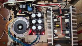
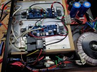
Finally got together everything and tried how it sounds. As my first diy amp it sound not bad. Will need to do more testing, but so far I like it. Running on 400 va 34 ac to 46vdc. 6x 8200uf Nichicon LKS. Soft start board, speaker protection board ( without it can play for half minute on capacitors only). It is not fully assembled yet. Trying to organize cables.
Attachments
Hi Yuradams,
What capacitor board, soft start and speaker protection are you using?
Thank you - z
What capacitor board, soft start and speaker protection are you using?
Thank you - z
Hi Yuradams,
What capacitor board, soft start and speaker protection are you using?
Thank you - z
All bought on aliexpress. Rectifier comes with schottky diodes but without capacitors. Soft start and protection boards comes with its own power supply on board(110v). For soft start you can use low amperage push button switch( works with self locking and self reset switch). Also has thermal protection circuit with sensors included. Works Good.
Speaker protection board also has delayed turning on and disconnect speakers when no supply ( before it was running for half minute on capacitors). It works and no issues for now.
Hi,
here is the hp protection that I have installed.
30A High power amplifier speaker protection board AC110V-220V | eBay
here is the hp protection that I have installed.
30A High power amplifier speaker protection board AC110V-220V | eBay
Attachments
Hi,
here is the hp protection that I have installed.
30A High power amplifier speaker protection board AC110V-220V | eBay
Looks good.


Very nice job yuradams!!!
I have not yet added and change the capacitors.
For now the sound is excellent.
I have not yet added and change the capacitors.
For now the sound is excellent.
Very nice job yuradams!!!
I have not yet added and change the capacitors.
For now the sound is excellent.
Thanks. It plays very good.
But I have a problem with my alps potentiometer on input. I either connected it wrong or got wrong one.
I am playing music from volumio through allo boss dac. If my alps is on about 20% of volume and volumio 100% - buzzing noise from speaker. But 20% on volumio and 100% on alps - no noise at all but same level of sound. When putting on pause - no noise for 20 sec and then noise. Shorting input- no noise . Was trying to move wires away from everything - no change.
It is rk27 alps 50k from mouser.
- Home
- Amplifiers
- Solid State
- L12-2 CFP Output amp 120W*2 8R