Thanks Berlusconi for the information and your comments about bias and DC drift.
With this socket I use a rectifier with servo controller (LF353). I changed the 2 big Elna fake capacitors by Rubycon that I had and of higher capacity .. I also changed the 2 output condos (small) by Nichicon.
AC-DC LM317 LM337 LF353 Servo Rectifier Filter
Thank you denbret, I have ordered the same socked as I have one spare Op Amp, then I will inform you on results.
With this socket I use a rectifier with servo controller (LF353). I changed the 2 big Elna fake capacitors by Rubycon that I had and of higher capacity .. I also changed the 2 output condos (small) by Nichicon.
AC-DC LM317 LM337 LF353 Servo Rectifier Filter
If so, you are not using 1k constant r19? With 1k- R19&R10 gives less than 15ma idle current (not theoretically, measured). I have changed R19 with trimpot and I'm using 10ma idle current (0.1 ohm R20,R13 and 1mv over them). note that I tried 50+ma idle current, I didn't hear any change in sound. Only output transistors warm up
Some sellers are listing this amplifier board as Class-A. So I assumed that the amp would work in Class-A mode until it runs out of bias current. I will lower it using a trimmer and see how that works.
Remember that this has CFP output. If you increase the bias, technically you increase switching distortion. If you reduce the bias, well, you have another distortion A big dilemma.
But in my observation, those who have sensitive hearing or very experienced with audio tend to prefer lower bias (And so it seems with the designer of this L12 amp).
With your high bias current, try trimming the bias (must have a trimmer) while listening to the best bass sound you are familiar with. Everyone can perceive bass quality well. Expect better bass with lower bias.
Would it be possible to see the distortion on a scope? Would it depend on the speaker impedance?
Edit: BTW, my listening levels are pretty low, it seldom goes above 90 dBA (in a medium sized room).
Last edited:
Would it be possible to see the distortion on a scope? Would it depend on the speaker impedance?
Yes, of course. Speaker impedance I think has little direct effect (impedance affects current, current affects distortion).
The bias setting is actually critical (only if your ears are sensitive). It's like tuning a radio signal, there is just one right amount. Oscilloscope may be needed. But I just used ears. As a rule of thumbs, you want highest bias possible (to get benefit of a class-A amps sound) but the right amount depends on the transistors used. With slower output transistors you will need to bias lower than when you use faster transistors...
I use old NEC transistors (60MHz). The designer of this L12 seems to prefer faster transistor too for this topology. There is advantages and disadvantages.
Of course, it is possible to see distortion, but information is limited because oscilloscope is working in time domain. Another type of instrument, Spectrum Analyzer, provides information in frequency domain. That is adequate instrument for measuring harmonic distortion. My oscilloscope may perform FFT analysis, but has limited capabilities. Once in the future I might invest substantially in Spectrum Analyzer.....
Would it be possible to see the distortion on a scope? Would it depend on the speaker impedance?
...
Despite of limitations, based on my measurements I can say that this midget board is awesome in that department, even when compared to more expensive packages. Don't be fooled into thinking that more expensive necessarily results in "better". This board is based on "Blameless Amplifier" design by Douglas Self. This fact and many other happy users indicate that you've made an excellent deal: for about 30 bucks you've got an awesome amplifier.
I have added a 1k potentiometer in series with R19 and quiescent current is now about 30mA and it sounds really good. This is still an experimental setup and I will tune it more precisely in its final chassis.
Thanks guys!

Thanks guys!
I have added a 1k potentiometer in series with R19 and quiescent current is now about 30mA and it sounds really good. This is still an experimental setup and I will tune it more precisely in its final chassis.
From the first page, the designer use LAPT from Sanken SA1186. I just checked the fT is 60M, same with mine. Find the highest fT for the output, especially when the cct has been made to work with such fast output transistor (it is not automatically). By using such transistor, you can increase the bias more than just 30mA. Mine is always hot when using such transistors.
Hi,
sorry, I can't follow You. What has a transistors Ft to do with the bias current?
The choice of transistors was made here due to their rather low input capacitance, which forms a RC lowpass with the driver transistors collector resistors.
It just happens that these low capacitance transistors are also very fast transistors.
jauu
Calvin
sorry, I can't follow You. What has a transistors Ft to do with the bias current?
The choice of transistors was made here due to their rather low input capacitance, which forms a RC lowpass with the driver transistors collector resistors.
It just happens that these low capacitance transistors are also very fast transistors.
Yes, with a huge amount of capacitance the bandwidth will be limited. Bandwidth also is a function of a lot of things/variables. We want the bandwidth at the current we are operating the device on...
So basically it was not an ideal causal-effect. With such fast transistor we will normally meet stability issues and running high bias will also probably help. So, "fast transistor <--> higher bias" is a rule of thumb. There are a lot of reasons why I found this empirically true with this topology. Please note I'm talking about this topology.
If you read the first page you will read that the OP relate ultra-high speed with CFP switching distortion. Note also that CFP crossover distortion is different animal than the usual class-B crossover distortion.

I have built these boards, and have to agree, the sound quality is faultless IMHO. I also purchased a Bryston clone ps pcb from Electronic-mall (ebay) and it is a godsend...combines dual mono, soft start and speaker protect, although i had to find a substitute tranny for the soft start, as it specifies a 220v unit. Im using 2 toroids of 145 va each, which is just adequate. Again, cant fault it. Sounds as good as any class AB amp ive heard.
Attachments
I just got a set of L12-2s. Everything seem ok, except for the power-resistors included. From reading this thread it seems like most of your boards are using either 0.15 or 0.22 Ohms. My boards were shipped with 0.10 ohms resistor.
Will the design work well with those 0.10-resistors or would you suggest me to have them replaced by 0.15/0.22?
/Niclas
Will the design work well with those 0.10-resistors or would you suggest me to have them replaced by 0.15/0.22?
/Niclas
They continuously drop the value of output resistors 🙂 I don't think there will be any audible change.
They continuously drop the value of output resistors 🙂 I don't think there will be any audible change.
Ok. So I keep them 'as is'. Thanks! 🙂
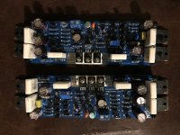
Can someone please post a picture of how the potentiometer is soldered on the board? I am mounting these boards on the sides of the case (sides are built-in heatsinks), and it would be nice to be able to access the potentiometer without much of disassembly.
Hanair, I assume you put your boards vertically with power transistors on left and right side. If so please put R19 resistor of 1K5 value normally from components side and add to it 5K potentiometer from the other = soldering side vertically. You will have access to it from the top.
What I also did - I left emiter legs of transistors Q9 and Q5 uncut and straight - it is easy to connect there multimeter probes from the back and measure idle current.
What I also did - I left emiter legs of transistors Q9 and Q5 uncut and straight - it is easy to connect there multimeter probes from the back and measure idle current.
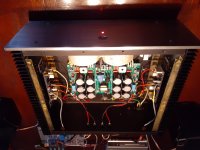
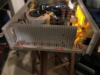
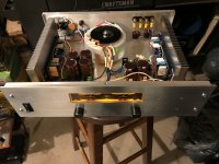
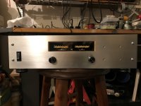
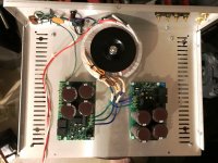
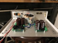
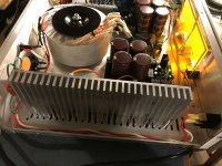
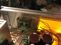
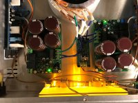
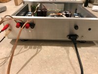
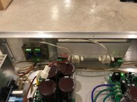
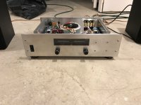
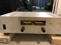
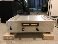
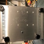
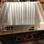
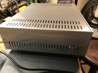
Finished Chassis for L12-2
It's been a workout! I drilled, cut and filed all the holes to fit everything.
I did the few mods recommended by members of this forum.
I set the Bias to 8.3mv or 16.6 across the collectors.
Power supply is an AnTek AS3430 30V 10A/60VCT 300VA Low Noise Audio Toroidal Power Transformer.
Rectifier Filter Power Supply Board w Speaker Protection 50V/6800UF kit. 2ea.
Had to build Power supply board for the VU LED lights. It's set at 2vdc.
Cassis came from pimetalproducts HiFi DIY Audio amp chassis 20-16124N
Volume idea is from Elliott Sound Products, works perfect!
VU meter circuit is driven from speaker level output. It's an old circuit, requires no power supply, each meter is set to 100watts to 0dB.
The Rail voltage is +-43.1 vdc with 15mv ripple on each rail.
DC offset is Lt ch...11.5mv. Rt ch...10mv
Unit is dead quiet at idle.
Now onto the pre-amp project😛😀
Attachments
-
 IMG_1146.JPG458.1 KB · Views: 277
 -
 IMG_1145.JPG494 KB · Views: 286
 -
 IMG_1144.JPG480.1 KB · Views: 266
 -
 IMG_1143.JPG395.3 KB · Views: 279
 -
 IMG_1106.JPG696.8 KB · Views: 309
 -
 IMG_1105.JPG568.1 KB · Views: 424
 -
 IMG_1103.JPG403.5 KB · Views: 418
 -
 IMG_1102.JPG433.7 KB · Views: 415
 -
 IMG_1100.JPG472.4 KB · Views: 413
 -
 IMG_1099.JPG445 KB · Views: 428
Last edited:
More😀
Attachments
-
 IMG_1163.JPG502.9 KB · Views: 154
 -
 IMG_1165.JPG496.7 KB · Views: 145
 -
 IMG_1166.JPG456.3 KB · Views: 137
 -
 IMG_1167.JPG602 KB · Views: 142
 -
 IMG_1162.JPG561.8 KB · Views: 160
 -
 IMG_1161.JPG576.9 KB · Views: 145
 -
 IMG_1156.JPG428.1 KB · Views: 145
 -
 IMG_1158.JPG452.5 KB · Views: 137
 -
 IMG_1154.JPG354.1 KB · Views: 139
 -
 IMG_1153.JPG464.3 KB · Views: 187

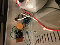
For ac voltage in, filter may be like that;
4.7nf, safety standards X1 Y2 400v (I used 2000volts)
330nf 275 volt, Polyester (X2?)
* and 1 turn for input ac cables in ferrite ring
If anybody advice better values?, those values copied from a PSU.
4.7nf, safety standards X1 Y2 400v (I used 2000volts)
330nf 275 volt, Polyester (X2?)
* and 1 turn for input ac cables in ferrite ring
If anybody advice better values?, those values copied from a PSU.
Last edited by a moderator:
Sound
SO, What I can tell is if the bias is closer to 7mv, it sounds a little flat and distorted, IMO. But when its up to 8 or so mv, it seems to sound brighter and less distorted but, there is more heat. (Just a little warmer). I've only played it with a DVD/MP3 player which has no tone or volume controls.
Does giving it, and how much can I give the bias more without destroying it? 9mv?
Oh, it does get very loud.
mdardeniz, where would those components be installed?
Pic?
- Home
- Amplifiers
- Solid State
- L12-2 CFP Output amp 120W*2 8R