So 17.6mv (.0176) divided by .2 (resistors in series) = 88ma. So if you want 40ma per transistor... Would I take total 88ma and divide it by 4 transistors? 22ma each?
No, it's not like that. The top half is in series with the bottom half. So you can calculate either the top half or the bottom half.
There are 2 collector resistors and there are 4 emitter resistors per channel.
The current at each of the 2 collector resistor is the same. If the current is 80mA then each of the 4 transistors (e.g. measured at the emitter resistors) get half of it (shared by 2 transistors), which is 40mA.
Disregard...this...So 17.6mv (.0176) divided by .2 (resistors in series) = 88ma. So if you want 40ma per transistor... Would I take total 88ma and divide it by 4 transistors? 22ma each?
After thinking about it and looking at Calvins PCB and knowing we want about 40ma for each transistor...this works out.
So Calvin measures over R13 OR over R20, not both!
On his PCB, it shows the Collector resistors at 0.1 ohm.
So there are a pair of transistor on each side that a 0.1 om resistor is connected between the collector of the pair and the speaker output.
So his formula 8.8mV (.0088 divided by 0.1 = .088 amp or 88ma. That is 44ma for each transistor on that side.
OK, I think I'm clear... Hope this helps others.
Thanks johnego for making me think!!!
Last edited:

Hi, Calvin says "35-40mA for a pair of output transistors suffices". Total 40ma is enough, not for each transistors.
If current 40ma and old schematic resistance 0.22 ohm(in kit 0.2 ohm). So, voltage on resistor(R13 or R20) max 8.8 mv (or 8.0mv). For 0.1 ohm resistor, only 4 mv.
Speakers not connected when you measure the voltage, so current on the two output resistors are the same as 40ma max.
If you use more than this, transistors will be hot. And I didn't see any difference in sound between 40ma or 10ma?
(note: in this schematic R5 is wrong.it must be connected to base of Q1. nobody wrote up to now 🙂
Last edited:
If you have 0.22 ohm collector resistors...and do the math
?mv divided by .22 = .088 (88ma)
.22 X .088 = .019
.019 divided by .22 = .088 (88ma)
So 19mv measured across one of the .22 resistors.
He should have shown this...
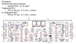
But if you look at the PCB layout from him, it has 0.1 ohm resistors and it says to measure 7.7 to 8.8 mv across R13 OR R20...NOT BOTH...
?mv divided by .22 = .088 (88ma)
.22 X .088 = .019
.019 divided by .22 = .088 (88ma)
So 19mv measured across one of the .22 resistors.
He should have shown this...
But if you look at the PCB layout from him, it has 0.1 ohm resistors and it says to measure 7.7 to 8.8 mv across R13 OR R20...NOT BOTH...
Attachments
OK, so between emitters of Q5 and Q9 having 0,22 collector resistors it should be 2x 19 = ca 38 mV
R5 is wrong.it must be connected to base of Q1. nobody wrote up to now 🙂
The effect will be paralleling the 100 Ohm resistor, lowering a bit such that the LTP current is a bit higher.
Hello Calvin, Can you clarify your L12-2 Schematics Mods Trim and Probs PDF.
The schematic shows 0.22 ohm resistors and your saying bias 35 to 40mA (7.7 to 8.8mV) OVER R13 AND R20!
Don't you want 35 to 40mA for each of the transistors? So 70 to 80mA?
This should say OVER R13 OR R20. People think you mean across both resistors so they are setting it to low.
To get 77mA to 88mA across .22...
17mV divided by .22 = 77mA
19mV divided by .22 = 88mA
So that's about 38 to 44 mA for each transistor.
Also the PCB layout shows 0.1 ohm resistors.
You say to measure across R13 OR R20...
If I'm doing the math correct...
mV across each resistor...
7.7mV divided by .1 = 77mA
8.8mV divided by .1 = 88mA
So each of the two transistor will get half of this..
38.5mA to 44mA
Correct?
I'm reading this thread from the beginning and got this on post #92 by LJM:
"Because CFP output make the distortion of the voltage range. Are lower than those of ordinary amplifier. So. More static current does not have a better performance. 10-20 ma. Is the ideal, the minimum distortion performance. Because of the existence of switch distortion."
So it is clear what bias is optimum for this module. For issues found by Berlusconi, that's strange. Not many people know how to design amplifier like this.
On post #92 LJM also suggests to cut the green 100pF. I believe it is the RC compensation on the LTP (Because the 100p Miller cap is required). It is one reason why I disagree with the LTP design. Another one I disagree is the current mirror but that's a standard design...
The two diodes made of small signal transistors on the LTP is for trimming. Different diode have different behavior so if LJM specified 2SA1015 diodes, don't change with other transistors/diodes.
The two diodes made of small signal transistors on the LTP is for trimming. Different diode have different behavior so if LJM specified 2SA1015 diodes, don't change with other transistors/diodes.
Hi,
iIrc I used to measure across both emitter resistors, R13+R20.
Reason was to increase measurement accuracy.
For one are the tolerances of low-ohmic resistors typically large and for second is the measurement error for typical 3.5-4.5digit DMMs quite high in those low-voltage ranges.
****here was a lengthy explanation followed on how to derive the measurement error for low input voltages for two DMMs and why it can be easyly a decade higher than the specced %. Unfortunately diyaudio sent the message into oblivion**** 😡
@90scaraudio: Your Qs are probabely answered in #95-#110
@mdardeniz: Thank You for pointing to the schematics error.
In all those years no one -me included- seems to have noticed this hoppala 😉
jauu
Calvin
edit: a updated schematic of V.4 could be useful. Anyone volunteering?
Last edited:
edit: a updated schematic of V.4 could be useful. Anyone volunteering?
I'm still reading posts from 2014 of this thread. Do you still like this amplifier? For class-B it will be hard to beat but class-A have benefit in the ease and relaxing nature of it, so I have moved to class-A. I also found that Latfet is better than BJT in CFP. I'm using NEC output transistors with fT from 60MHz to 80MHz and hfe way above 200 and matched, but Latfet just sound better.
Hi,
Yes, what´s not to like about such a priceworthy little amp that sounds so well and is easily tuneable? 😉
No doubt, that there may be ´better´ amps around and everybody is perfectly entitled to use something different.
But that doesn´t render these amps ´bad´ at all.
btw. which FETs do you use ... and is matching of pairs or quads required? The Vgs differences of FETs are typically larger than the Vbe tolerance of BJTs.
jauu
Calvin
btw. added the V.4 schematic to my website .... please notify me if you find errors.
Last edited:
btw. which FETs do you use ... and is matching of pairs or quads required? The Vgs differences of FETs are typically larger than the Vbe tolerance of BJTs.
I don't use matched latfet (it's expensive! 😀). I even use the cheap J162 variant for prototypes. Yes, the Vgs. I think that could be one reason IRFP and some others often do not sound good at all in CFP. But Latfets do not react on Vgs change like BJTs do on Vbe.
btw. added the V.4 schematic to my website .... please notify me if you find errors.
Haven't seen your website before (I think). Will check...
btw. added the V.4 schematic to my website .... please notify me if you find errors.
Is that LJM's modification or yours? Or LJM's but without his confirmation? Is he still active here? I couldn't see many differences.
I read from his post from 2014/2015 that he suggests removing the output resistors because he tried to remove resistance as much as possible from the output. While that is true especially with low drive CFP, I disagree. In my experience high output resistor (I use 0.47) will make sure CFP crossover distortion low. But if low crossover distortion can be made with no output resistor, then that will be great (but I believe not automatically by just reducing it)
I'm reading this thread from the beginning and got this on post #92 by LJM:
"Because CFP output make the distortion of the voltage range. Are lower than those of ordinary amplifier. So. More static current does not have a better performance. 10-20 ma. Is the ideal, the minimum distortion performance. Because of the existence of switch distortion."
So it is clear what bias is optimum for this module. For issues found by Berlusconi, that's strange. Not many people know how to design amplifier like this.
Thanks for this...I missed it.... So the 10-20ma, is this for each transistor or for the pair. Reason I ask is with .1 ohm resistors, if I measure 2mv across it that gives 20ma. So each transistor is at 10ma? Or do I set it to 2-4mv to get the 10-20ma for each transistor?😕
Thanks for this...I missed it.... So the 10-20ma, is this for each transistor or for the pair. Reason I ask is with .1 ohm resistors, if I measure 2mv across it that gives 20ma. So each transistor is at 10ma? Or do I set it to 2-4mv to get the 10-20ma for each transistor?😕
10-20mA per each transistors (measured at emitter resistors). Or 20-40mA per pair (measured at collector resistor).
Do you know Kirchoff law? We have 2 emitter resistors and 1 collector resistor. Sum of currents in the emitter resistors will be the current at the collector resistor (more or less).
Normally with EF output we set bias 40mA per transistor. With CFP it is lower (10 to 20mA). But I don't understand why you people ask this as in the module there is no trimmer?
In CFP amps it is not flexible to change parts (e.g. resistance in the Vbe multiplier) as in EF amps.
I don't understand why you people ask this as in the module there is no trimmer?
@johnego - we ask because Calvin has suggested a trimmer.
@johnego - we ask because Calvin has suggested a trimmer.
- Home
- Amplifiers
- Solid State
- L12-2 CFP Output amp 120W*2 8R