I don't understand why you people ask this as in the module there is no trimmer?
@johnego - we ask because Calvin has suggested a trimmer.
Oh, I see.
Thanks Calvin,hey ... it´s not my fault ...
...´twas broken already 😀
Raw L12-2, including other LJM boards, without the potentiometer have 3 (three) major issues, two of them can be easily rectified with the adjustment of bias, as you have suggested. Without any furher ado, just by following a simple procedure.
Danke schön. (Ger. = Thank you.)
L12_Version4 Design Review
I just simulated L12_V4 as found in Calvin's website and compared with my new CFP design (completely different topology) that I just finished and will build tonight until tomorrow.
I attached the FFT of both amps for comparison. Not many differences.
All other factors are good except for one thing: crossover distortion.
L12_V4 (10kHz) simulated THD is 0.0072% while mine is 0.0089%. This is pretty standard for CFP and is not critical. It is possible to reduce distortion of such CFP amplifiers to 0.002% at the expense of crossover distortion, but is usually not preferred by my ears.
The L12_V4 bias is only 16mA (per transistor) but the crossover distortion is "unacceptable" (by my standard). My amplifier design is biased 31mA but the crossover distortion is so much better.
Like I said in my previous post that it is not easy to reduce or remove the output resistors without sacrificing crossover distortion performance (it is possible with total redesign). I think 0.22 output resistors will give better crossover distortion.
Attachments

My amplifier design is biased 31mA but the crossover distortion is so much better.
Like I said in my previous post that it is not easy to reduce or remove the output resistors without sacrificing crossover distortion performance (it is possible with total redesign). I think 0.22 output resistors will give better crossover distortion.
May I ask about how did you measure crossover distortion?
May I ask about how did you measure crossover distortion?
Not measure, but simulate. Before you think this is not possible, let me tell you something cool about simulation...
I like to use ears in building speakers since I was a kid. Even until today when I have the tools to measure and simulate I still like to throw some inductors/capacitors and just listen by ears (I have expectations)...
One day I tried various capacitor values for a bootstrap capacitor and I found that bigger is better (listened by ears) so I used 1000uF. The other day I thought bootstrap capacitors must be big so I used the same 1000uF but the sound got worse! So I checked with simulator and I started to find the cool phenomenon...
If C=220uF THD=0.00111116%
If C=470uF THD=0.00111117%
If C=680uF THD=0.00111118%
So with above simulation, the circuit wants a smaller capacitor for the bootstrap. You may think that 0.0000000 something wouldn't be audible but that's the cool thing about this. The measured THD might not be that small but the point is it is audible. So in this case I will use 150uF.
Same with capacitor at Vbe multiplier and others. Simulator will tell you if the distortion graph is linear or exponential, meaning there is optimum value if exponential (such as in CFP crossover distortion).
With simulator you will learn and understand what causing the crossover distortion (which you can't do with oscilloscope) so what you do next after simulation is simply to adjust the actual circuit until critical operating point conditions are met (So this is not as simple as using ONE trimmer, you may need THREE, but I don't use trimmers, just change/parallel the resistor or change transistor with different hfe or Vbe).
BTW, I just remembered that the original output transistor used by LJM is the fast 2SA1186. It is a completely different beast than the one used in Calvin's or my simulation (2SA1943/C5200).
When I built my best class-B amp, I couldn't find the model for the fast transistors so I simulated using 2SA1943/C5200 and it took me some time to adjust and listen to the modifications when I changed the output transistor to fast NEC devices.
My new CFP is about to finish. I don't believe it can beat my best amp, as my best amp really shine EXACTLY due to the fast NEC output transistor.
Volume or gain pot
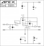
Anyone see anything that can be added to this buffer amp or will it work as is?
After reading through the forums, I quickly realized that if I'm going to use potentiometers for these L12-2 v4 amps, they should be a buffer type circuit.
The amp sounded terrible with just pots before the input. When I go straight in without pots, it sounds very good. Even with the bias set to 1.3-1.7mV per pair.
Any thoughts?
Attachments
Hi,
For me, L12.2 direct at the output of the DAC, it is not optimal.
I am using an OPA1692 and a 10k pot between the DAC and the OP (direct to amp). The sound is perfect.
For me, L12.2 direct at the output of the DAC, it is not optimal.
I am using an OPA1692 and a 10k pot between the DAC and the OP (direct to amp). The sound is perfect.
Hi,
For me, L12.2 direct at the output of the DAC, it is not optimal.
I am using an OPA1692 and a 10k pot between the DAC and the OP (direct to amp). The sound is perfect.
Other than that, would this be an ok circuit?
Other than that, would this be an ok circuit?
I'm not sure I understand correctly ... correct circuit ?? The L12.2 ??
I'm not sure I understand correctly ... correct circuit ?? The L12.2 ??
The buffer amp from Apex🙂
There is a misunderstanding, I don't have the Apex buffer. It is rather an OP OPA1692. 🙂
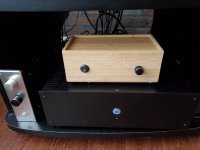
it is a box of bamboo kleenex!!! 🙂
it is a box of bamboo kleenex!!! 🙂
Attachments

Last edited:
There is a misunderstanding, I don't have the Apex buffer. It is rather an OP OPA1692. 🙂
Do you have the circuit that you used?
Do you have the circuit that you used?
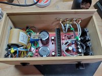
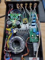
The circuit is simple, I don't have a diagram. The output of the DAC goes directly to the 10k volume pot and the output to the OP, output of the OP to the amplifier. Nothing else. I have 2 PSUs with 10k pot and OP (OPA1692). I will compare the quality of the 2 PSUs, I put a photo of my other PSU + OP.
Attachments
After reading through the forums, I quickly realized that if I'm going to use potentiometers for these L12-2 v4 amps, they should be a buffer type circuit.
The amp sounded terrible with just pots before the input. When I go straight in without pots, it sounds very good. Even with the bias set to 1.3-1.7mV per pair.
Any thoughts?
Yes, the amp has low AC impedance. To my ears, all systems sound bad with 10k pot in front of the amplifier. But the standard is to have 47k resistor instead of the 10k resistor in front of the amplifier's LTP. But you cannot change/increase this 10k resistor in this CFP amp.
If your ears is sensitive enough to appreciate the sound of this CFP amp, I think you should not use NE5532. Or you can create discrete JFET buffer before and after the pot.
So use a jfet op-amp like the old TL072's or is there better options?
So use a jfet op-amp like the old TL072's or is there better options?
I meant discrete JFET circuit like what you'll find in Pass Labs active crossover. Discrete JFET is a solution for those who cannot accept the low transparency of op-amp circuit. A good opamp circuit can be very expensive (the opamp and the power supply).
For my part I find the sound exceptionally transparent. It's very difficult to have more without falling into an overly analytical sound.
You have to try the OPA1692 (or OPA1656) you will change your mind.
You have to try the OPA1692 (or OPA1656) you will change your mind.
Last edited:
For my part I find the sound exceptionally transparent. It's very difficult to have more without falling into an overly analytical sound.
You have to try the OPA1692 (or OPA1656) you will change your mind.
So I would have to do some smd work🙁 I do see to use DIP8 ADAPTERs. Do you think I would have to do anything special to this circuit? or use it as is?
Attachments

Last edited:
- Home
- Amplifiers
- Solid State
- L12-2 CFP Output amp 120W*2 8R