You need to feed it (the AC PSU module) with a transformer with 18-20VAC output. Here's an example : Page Not Found - Aliexpress.com
The version with 0-9V, 0-9V is the one you need and you wire those two secondaries in series to give 18V.
The text you quoted is referring to the DC version of the power supply but you'll need the AC version if you don't already have a DC output PSU (for example an EI wall-wart with DC output). Here's the AC PSU : Kubelik NOS DAC kits
Don't worry about 'stupid' questions 😛
Thank you!
1) Would it be possible for you to sell us newbies a everything we need to get it up and running kit? I’d hate to screw this up some how and burn down the house by using the wrong power supply lol!
2) Wood a wooden enclosure for this dac be ok?
3) Would you be willing to sell a coax input to i2s board as an addition for this kit?
Thanks again for answering all my questions! I’m kind of excited to try my hand at smd soldering. I hope it’s similar to drag soldering tsop chips.
2) Wood a wooden enclosure for this dac be ok?
3) Would you be willing to sell a coax input to i2s board as an addition for this kit?
Thanks again for answering all my questions! I’m kind of excited to try my hand at smd soldering. I hope it’s similar to drag soldering tsop chips.
1) If you look at the first post in this thread I talk about the extra things you need and which ones I'm offering to supply. Practically anything except the case (because that's heavy) I'm able to provide (oh and not transformers due to them being heavy too).
2) A wooden case would be fine in principle, some ventilation in the case would be a good thing. Overall the dissipation isn't very high, around 2W for the DAC.
3) See the first post where I talk about a recommended S/PDIF input board.
2) A wooden case would be fine in principle, some ventilation in the case would be a good thing. Overall the dissipation isn't very high, around 2W for the DAC.
3) See the first post where I talk about a recommended S/PDIF input board.
Thank you! Somehow you remind of my professors in University many years ago, very knowledgeable!
R18 is zero ohms. This puts 10vdc at the output. I guess I'm missing something. Maybe R18 should not be installed?
Last edited:
You're right - R18 and R64 are not installed unless you want to use off-board coupling caps at the output. Those 0R resistors bypass the on-board 'lytics for those who want to gild the lily. When you fit R18/R64 you must use off-board caps.
I plan to install a 2 of these in a 2 chassis pre/phono/dac set, one chassis has all of the power supplies.
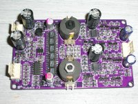
Maybe you can help with a question. I would like to use a DAC input rotary switch as shown. My plan now is to use an interface board for each input and switch lrck/data/bck to DAC for input choice. I prefer a interface board where I can connect all inputs and use the rotary switch to send a switching signal to select the input.. Maybe this board is available?
Maybe you can help with a question. I would like to use a DAC input rotary switch as shown. My plan now is to use an interface board for each input and switch lrck/data/bck to DAC for input choice. I prefer a interface board where I can connect all inputs and use the rotary switch to send a switching signal to select the input.. Maybe this board is available?
Attachments
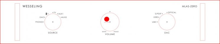
You might not need a board if your I2S wires are short, say under 20cm totally. Then you could use a switch like this : https://www.mouser.com/ProductDetail/Alpha-Taiwan/SR2513F-0304-19F0A-T-N?qs=yA6kp8fx8Y5bvs5n3EvHSA==
If its impractical to keep the I2S wires that short then you'll need an electronic switch board. I will have a look around to see if there's anything suitable.
This looks like it could work : https://www.aliexpress.com/item/4000183180212.html?spm=a2g0o.productlist.0.0.2e325cb3CS94kt&algo_pvid=06d645e9-f776-4303-82f4-0d75b4555440&algo_exp_id=06d645e9-f776-4303-82f4-0d75b4555440-3&pdp_ext_f=%7B"sku_id"%3A"10000000672344041"%7D
Thanks. I can try out the switching module. 20cm wire might be a challenge. what about optical, it would still need the interface module? Have some learning to do, first dac build for me, also researching I2S.
When you ask 'what about optical?' do you mean you want to switch between several optical inputs? If so that's probably best done at the stage where the signal is logic level S/PDIF, then it only needs a single pole switch (as opposed to 3 pole for I2S). The signal coming out of the Toslink receiver module is logic level S/PDIF. Then after the switch you'll need an S/PDIF to I2S converter IC (such as WM8805, DIR9001, CS8416 and the like).
My desire is to switch 2 optical, one spdif, one USB or 2 usb, 1 optical, one spdif. I like what you said about switching the logic level and with the use of a single pole switch.. Need to examine this more.
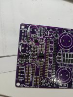
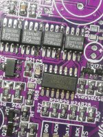
Regarding the yellow diode orientation.
the extra white marking on pcb nearer to the TL 431 correspond to the green marking of the yellow LED?
the extra white marking on pcb nearer to the TL 431 correspond to the green marking of the yellow LED?
R68 is the phase selection - mount a 0R resistor to the left for non-inverting, to the right for inverting (180o phase). The LED has a small triangle underneath which points to the negative (to the right, towards TL431) and that's the green dot on the yellow LED.
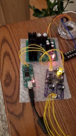
After much delay, today I started assembling the Kubelik kit.
Step 1 completed, voltages measured OK, yellow LED lights 👍
Before moving on, I had to look back for some guidance, so here are the links of all I could locate:
CORRECTED STUFFING GUIDE
https://www.diyaudio.com/community/...-rbcd-multibit-dac-design.324933/post-6768101
SCHEMATIC and GERBER FILES
https://www.diyaudio.com/community/...-rbcd-multibit-dac-design.324933/post-6747005
MOUSER BOM
https://www.diyaudio.com/community/...-rbcd-multibit-dac-design.324933/post-6748194
SOLDERING GUIDE
https://www.diyaudio.com/community/...-rbcd-multibit-dac-design.324933/post-6761358
TRIMMING OFFSET
https://www.diyaudio.com/community/...-rbcd-multibit-dac-design.324933/post-6769203
George
- Home
- Vendor's Bazaar
- Kubelik NOS DAC kits