You may solder pin 7 to it’s pad below it (I have done so). But the pad is not connected to anything.
Abraxalito prefers pin 7 floating. We had this discussion in the past
https://www.diyaudio.com/community/...ts-with-pre-built-filters.354799/post-6578471
George
Abraxalito prefers pin 7 floating. We had this discussion in the past
https://www.diyaudio.com/community/...ts-with-pre-built-filters.354799/post-6578471
George
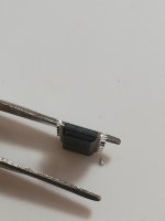
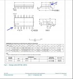
the 'dot' is referring to the silkscreen print on the board , which indictates pin1. You should be looking for the bevel on the side of the 74hc chip, and align this beveled side to the dot on the board.The problem arises as l can see a central dot marking on both ends of the 74HC!
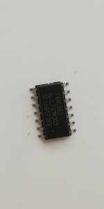
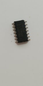
The bevel that's relevant to this discussion is one running down the long edge of the chip on the top surface, adjacent to the pins. Arrange the chip so that bevel is adjacent to the I2S connector. Or alternatively arrange the chip so the text reads top to bottom, in the same direction as you have for the DACs.
K... You see a bevel both sides whereas on your pix I can see clearly which side has the bevel, and that's one only, and again just looking at your pix.
So... either you are looking at the wrong thing, or you need help with your eyes.
Hence 2 advices:
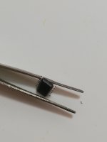
1- start looking from the relevant view to see where the bevel is. And that is not looking from the top of the chip, or not only. I would advise you look at the chip from its smallest side, so the bevel appears clearly to you, like a small roof seen from its side, if you follow me.
2- If point 1 is not enough, time to use magnifying glasses (I recommend these anyway with SMDs, at least to check that everything is OK). Or at least for the bevel bit take pix with a good phone and zoom into the pix later to identify better the bevel.
With all these chips you really have to find out 100% failproof how they fit, or it can be disastrous depending on the build. And again, a magnifying glass with lights is a good investment for small works like this one (and many non DIYA related ones. Not just to see bevels, but to check your soldering, legs can easily touch on chips. All IMHO
I hope this helps
Claude
So... either you are looking at the wrong thing, or you need help with your eyes.
Hence 2 advices:
1- start looking from the relevant view to see where the bevel is. And that is not looking from the top of the chip, or not only. I would advise you look at the chip from its smallest side, so the bevel appears clearly to you, like a small roof seen from its side, if you follow me.
2- If point 1 is not enough, time to use magnifying glasses (I recommend these anyway with SMDs, at least to check that everything is OK). Or at least for the bevel bit take pix with a good phone and zoom into the pix later to identify better the bevel.
With all these chips you really have to find out 100% failproof how they fit, or it can be disastrous depending on the build. And again, a magnifying glass with lights is a good investment for small works like this one (and many non DIYA related ones. Not just to see bevels, but to check your soldering, legs can easily touch on chips. All IMHO
I hope this helps
Claude
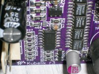
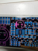
George, as ever, nice soldering work!
... And exceptional flux cleaning of the board. That's the bit I find most difficult, not from a functional but from an esthetical POV. May I ask what you used? Perhaps a strong spray to start with? Using only isopropanol and a teethbrush + rag I sadly don't get the same (clean) results between the chip's legs as you...
Enjoy music and let us know how it sounds
Claude
Thank you.
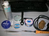
This is what I use. I find each of those (plus good lighting) as essential.
Flux cleaner is isopropyl alcohol. Then hard nylon brush rubbing, rug wiping, repeat again and again.
The humble toothpick is for removing the bulk of entrapped flux between the IC legs.
Not less than half an hour for cleaning this small board.
Cleaning is a necessary step preceding optical close-up solder inspection. It is also important for long term reliable operation of the electrical circuit
George
Attachments
Kp93300 ,
The bevel is only on one side and is very clear from your pictures. it is just bevel to look out for. no dimples or notches or whatever that you should get yourself to be concerned with.
The bevel is only on one side and is very clear from your pictures. it is just bevel to look out for. no dimples or notches or whatever that you should get yourself to be concerned with.
Attachments
Thank you all for the help. l understand now. I was not looking at the correct place. l was expecting to see a notch as indicated on the pcb. What the mind don't know, the eye donot see is very true for me.
The SOT resistor is fitted if you want to trim the offset voltage (internal, not at the output) down closer to zero. The procedure for doing that George linked to a few posts back. Its not necessary - when I've done it I haven't noticed any improvement in SQ.
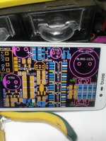
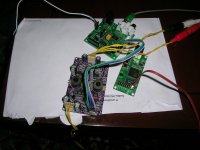
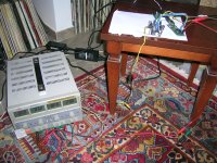
Wiring on the fly and initial functional tests.
I can say I am impressed with the Kubelik.
No hiss or any noise in idle, well bodied and overall balanced sound. Silk smooth on highs, full on bass.
In addition to that, it withstood the ultimate idiot’s test of connecting the power DC in reverse polarity.😵
 Abraxalito
George
I can say I am impressed with the Kubelik.
No hiss or any noise in idle, well bodied and overall balanced sound. Silk smooth on highs, full on bass.
In addition to that, it withstood the ultimate idiot’s test of connecting the power DC in reverse polarity.😵
AbraxalitoGeorge
Attachments
- Home
- Vendor's Bazaar
- Kubelik NOS DAC kits