Yes Claude, I have built the Phihex dac, which I use for listening to music from a laptop USB out. The USB to I2s converter for this, is the jlsounds I2SoverUSB v.III. It isolates the electrically noisy laptop (due to dead battery) from the Phihex DAC.You built the PhiDac as well if I remember well... how does that one sound in comparison to Phi DecaDac or any other DAC to your ears?
Now, the USB to I2S converter I connected to the Kubelik is not isolated and at the USB tests I run yesterday, a lot of noise mixes with the music, so for the time being I am not in position to compare those two.
What I commented on yesterday had to do with SPDIF signal from a Rotel RCD-9658X CD player.
George
Last edited:
Ah! I confess, I missed that... 😳Not a good moment for humor nautibuoy, wasn't it? 🙂
George
Last edited by a moderator:
I noticed that Richard prefers high value , 220uf dc blocking output caps. Is there any particular reason?
Good question!
Mostly its because I connect my DACs to my amps and those (at present) have transformers for input. Keeping a high value cap in series with the trafo's primary pushes its LF resonance below audible frequencies. With a lower value a bass hump appears in the frequency response.
There is also the issue that a film cap in that position couldn't be a very large value with the amount of PCB real-estate available. Maybe 2.2uF polyester would be about the limit.
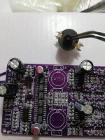
By all means secure the screws by glue or hot melt. As far as possible, don't move the ferrite halves relative to each other or the inductance value will change. Are you sure its the screw that's loose, not the ferrite core relative to the bobbin? The latter is very normal. Tprquing up the screw won't stop the play of the bobbin relative to the core. Once its soldered down, the PCB will hold both in position and there won't be any movement, that is if you tension the bobbin 'arms' sufficiently by applying pressure to each when soldering.
Mostly its because I connect my DACs to my amps and those (at present) have transformers for input. Keeping a high value cap in series with the trafo's primary pushes its LF resonance below audible frequencies. With a lower value a bass hump appears in the frequency response.
There is also the issue that a film cap in that position couldn't be a very large value with the amount of PCB real-estate available. Maybe 2.2uF polyester would be about the limit.
By all means secure the screws by glue or hot melt. As far as possible, don't move the ferrite halves relative to each other or the inductance value will change. Are you sure its the screw that's loose, not the ferrite core relative to the bobbin? The latter is very normal. Tprquing up the screw won't stop the play of the bobbin relative to the core. Once its soldered down, the PCB will hold both in position and there won't be any movement, that is if you tension the bobbin 'arms' sufficiently by applying pressure to each when soldering.
Last edited:
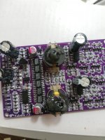
Check for the inductors pin pair on which the magnet wire is visible. This pair should be oriented to the inner side.
The other pair of pins is not connected to the inductor wire. Also the outer pads of the PCB are not connected to the circuit.
George
The other pair of pins is not connected to the inductor wire. Also the outer pads of the PCB are not connected to the circuit.
George
 for Abrax
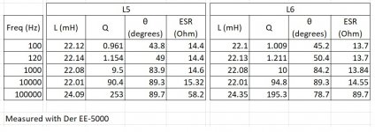
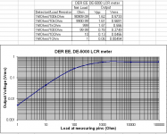
At lower frequencies I think the inductance goes up because the drive current used to measure increases, resulting in increased flux in the core and higher non-linearity. At 100kHz we're on the way towards the inductor's self-resonant frequency where it forms a parallel tuned circuit with its own stray capacitance.
BTW the inductors are made by my wife 😛
BTW the inductors are made by my wife 😛
l have been listening to Kubelik today.
l have an intermittent random distortion like the sound engineer editing the sound track. l have to listen intentionally to hear it and it is very subtle and last a second or less. This maybe my bad power supply as l am using an old printer adapter of 16 v dc and step up by buck converter. The transformer is not ready.
It has very low noise floor and l can only hear the tube hiss of my amp when not playing music. The sound is impressive with huge soundstage and mutiple layers front to back.
Attachments
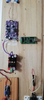
l want to report that the problem is the c media usb i2s converter. It is playing well with another pcm2706 converterl have been listening to Kubelik today.
l have an intermittent random distortion like the sound engineer editing the sound track. l have to listen intentionally to hear it and it is very subtle and last a second or less. This maybe my bad power supply as l am using an old printer adapter of 16 v dc and step up by buck converter. The transformer is not ready.
It has very low noise floor and l can only hear the tube hiss of my amp when not playing music. The sound is impressive with huge soundstage and mutiple layers front to b
l want to report that the problem is the c media usb i2s converter.
With Win7 I had low level artifacts with the CM6631 driver set to 16bits. On 24bits, no such issue.
Taobao now shows form-factor compatible PCM270X interfaces, such as this one : https://item.taobao.com/item.htm?sp...Exej3&id=620187891162&ns=1&abbucket=20#detail and this : https://item.taobao.com/item.htm?sp...SUhSt&id=624170500870&ns=1&abbucket=20#detail
The cmedia i2s converter gives a more detailed and 3 dimensional sound when compared to pcm2706. PCM 2706 has a warmer sound , bass less tight but vocal is more seductive.
The issue with c media present with Linux OS?
The issue with c media present with Linux OS?
Placed an order for a Kubelik kit today.
I have a USB interface but has anyone tried a Bluetooth to I2S interface, like this one;
https://www.ebay.co.uk/itm/254450121443?var=554090202683
I have a USB interface but has anyone tried a Bluetooth to I2S interface, like this one;
https://www.ebay.co.uk/itm/254450121443?var=554090202683
After some months, finally got around to finishing my kit.
Was fairly simple and enjoyable, start to finish maybe 3 hours, fairly straightforward and well marked (really, all those baggies precisely cut, well marked, etc..might have taken as much as it took to put the kit together, very nice (but your apartment must be littered with small baggies.. )
Tested all values on test points, everything fine from the get-go , but then i checked output and lo and behold 10V dc on the output.
Quick glance at the schematic shows two 0R resistors bypassing the DC blocking cap at the output, thus having DC again. Not sure exactly what their purpose is and why they're showed to be installed in the guide (or what to do with the ones marked SOT, or the how to select the phase resistor for the i2s shift register glue logic but i just put 0R to go to input A1 (first two squares)). Anywho no bigge issue solved in a second and on we go to listening.
I have to say sounds excellent. I really love this DAC, and at this price can recommend to anyone, abraxalito is doing the DIY community a big favour, especially the frugal audiophile. Another pro to some is no need for bipolar supplies. Plug in a single 20 and off you go.
That being said i have some other suggestions/questions...
1. only one GND on I2S input. I suppose done for space concerns/to keep the 4 pin connector. But really would have liked to see a 2x3, so each i2s line has it own separate current return path, in a twisted pair.
2.This one is more of a question, but not sure why some connectors are 90 degrees, and one is 0 degrees (straight up). Honestly i just straightened the 90 degrees one and now they all point up, not an issue just made me wonder if it has a purpose and i'll only realise i messed straightening them up later.
3. Not gonna lie, pretty big squeal on turn off...
4. I cheated a bit when i said it sounds great. It sounds great at really low volume (on headphones), in reality it begins to clip hard at around 0.1v (so says the DMM). At 0.15v its already making just fart noises, like someone recording a rock performance in the first row from their phone. Now since nobody else mentioned this i am assuming i just messed up somewhere. I thought maybe its the JLsounds board, but works great in any other dac. In the configuration sheet, i just used the standard I2S protocol (as for example an ES90xx dac). So i dont know, what the deal with that is, but yeah, im still feeling positive about this dac.
You could build a really neat little low-cost unit with this probably. Like those people on aliexpress, slap on a PCM 2706, in some generic case etc. JLCPCB is doing offers for pretty cheap smd assembly, and almost everything on the board is smd. Im just thinking out loud here, but this is a really neat little chip and abraxalito has been in the NOS tda1387 waters for a while. I guess hard part is getting the missus onboard with mass producing the inductors
P.S..merry christmas everyone!
- Home
- Vendor's Bazaar
- Kubelik NOS DAC kits