I agree, it will make everything easier to be seen, then you can apply fbk to iron remaining harmonics.I wonder if you would be better making your distortion measurements with the loop open.
Open to suggestions, how would I best tackle that?I agree, it will make everything easier to be seen, then you can apply fbk to iron remaining harmonics.
The SS tail Mr Steward has another advantage. I like DC coupling of the first stage to the LPT as it makes the LF stability better. However the ef86 plate operating voltage is very variable form device to device. Adding a CCS in the second stage prevents the LPT plate voltages being a function of the ef86 plate voltage.
Thru previous work I found that there is ~10 db stabilization of the Q point of a small signal pentode by the screen resistance. The difference between the bypassed & unbypassed stage gain measured on the bench is the indicator. Further stabilization of the Q point is provided by the cathode resister.
Thru previous work I found that there is ~10 db stabilization of the Q point of a small signal pentode by the screen resistance. The difference between the bypassed & unbypassed stage gain measured on the bench is the indicator. Further stabilization of the Q point is provided by the cathode resister.
Attachments
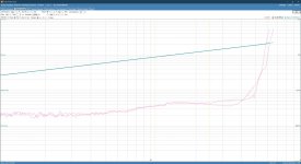
No worries Jan, you're here, that's all that matters! And yes, I didn't expect this either, although I need to revisit as I've obviously made changes to the prototype since then, so this may no longer be the case with the current iteration of the schematic.Sander, sorry to be late, but this caught my eye. To me that signifies that the distortion is not in the output stage. AC-removing the cathode resistors would increase output stage distortion but would also increase loop gain so the feedback can correct distortions anywhere in the loop.
The fact that the result is lower distortion says that it originates before the output stage.
jan
Yes, that part I understand, I'm just wondering what the best approach would be to measure the various sections in isolation?Cut the trace between NFB and C15.
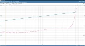
More on this, I'm trying out different ways of hooking up the cathode resistors on the KT88s. Have a look at the two configurations I just tried, and the resulting measurements. There's a clear difference, however with the bypass capacitors the distortion plot doesn't have the dip around 30W and is flattened out. Interesting, just not sure what sort of conclusions I can draw from this?Sander, sorry to be late, but this caught my eye. To me that signifies that the distortion is not in the output stage. AC-removing the cathode resistors would increase output stage distortion but would also increase loop gain so the feedback can correct distortions anywhere in the loop.
The fact that the result is lower distortion says that it originates before the output stage.
jan
Attachments
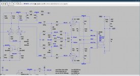
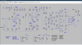
Alright, this is where I'm at at the moment, and I am running out of ideas to further optimize things. I've reduced the parts count and simplified the circuit around the LTP without any adverse effect on performance, or at least as far as I can see/measure. I believe it was Albert Einstein who said: 'Everything should be made as simple as possible, but not simpler' and I couldn't agree more. Thanks guys for all the helpful suggestions thusfar!
Attachments
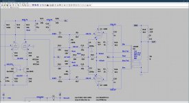
Actual anode voltages on the 6922 are lower, around 300V, I forgot to add these to the schematic, please see an updated schematic below. The voltages noted with a * are the measured voltages. So there's no problem, Also many manufacturers (JJ and Tung-Sol for example) specify a 400V Ua-max for the 6922/E88CC so we're nowhere near the max, with about 100V of headroom.What about reliability at 330Va?
Attachments
I don’t see the problem, the 6922 is routinely used, also in commercial designs, running at much larger current and anode voltages than I’m using here. If you worry about the longevity of the tube then I suggest you stay away from tube amplifiers as they all need their tubes replaced at some point, some more often than others.This 400Va is only at Ia= 0, which is not the case here. Maximum at Pa<0,8W is 250V
The 6922 is a long-life tube for 10.000h, in your amplifier a lot less with those voltages, it’s your choice for less reliabilty.
Nobody cares, least of all me.The 6922 is a long-life tube for 10.000h, in your amplifier a lot less with those voltages, it’s your choice for less reliabilty.
More on this, I'm trying out different ways of hooking up the cathode resistors on the KT88s. Have a look at the two configurations I just tried, and the resulting measurements. There's a clear difference, however with the bypass capacitors the distortion plot doesn't have the dip around 30W and is flattened out. Interesting, just not sure what sort of conclusions I can draw from this?
Here is an interesting read on that subject.
Here is an interesting read on that subject.
Attachments

Thanks John, I’ll be sure to give that a read!More on this, I'm trying out different ways of hooking up the cathode resistors on the KT88s. Have a look at the two configurations I just tried, and the resulting measurements. There's a clear difference, however with the bypass capacitors the distortion plot doesn't have the dip around 30W and is flattened out. Interesting, just not sure what sort of conclusions I can draw from this?
Here is an interesting read on that subject.
About the cathode capacitors for output tubes, there’s also VacuumState trick: use separate resistors for each output tube cathode, then use one capacitor for each output tube cathode, join the other side of the two capacitors together, then add a resistor with a value of 16% of Rk to ground. That proved to dramatically reduce IMD.
Thanks! I’ll whip that up tomorrow and see whether I see an improvement on the prototype.About the cathode capacitors for output tubes, there’s also VacuumState trick: use separate resistors for each output tube cathode, then use one capacitor for each output tube cathode, join the other side of the two capacitors together, then add a resistor with a value of 16% of Rk to ground. That proved to dramatically reduce IMD.
P.s. any suggestions for a gyrator load for the EF86 you mentioned earlier? I mean I can cobble something together, but if you have a proven design you’d like to share I’d rather hit the ground running.About the cathode capacitors for output tubes, there’s also VacuumState trick: use separate resistors for each output tube cathode, then use one capacitor for each output tube cathode, join the other side of the two capacitors together, then add a resistor with a value of 16% of Rk to ground. That proved to dramatically reduce IMD.
- Home
- Amplifiers
- Tubes / Valves
- KT88 PP - Dotting the Is, crossing the Ts