Thanks! I have something else on my mind, I’ll try it out tomorrow and report back.I tried dropping R33 to 390K to give bias of 100V to second stage but that's all I could find.
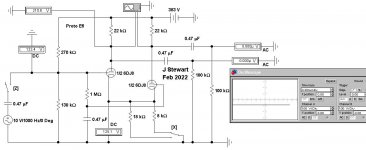
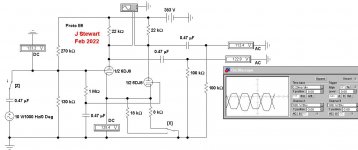
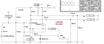
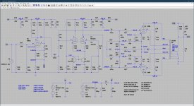
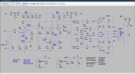
The Sims of the Proto E6 series shew circuit conditions with & without signal for both 8K & 18K tail resisters. The input DC level has been adjusted to be compatible with the plate of the first pentode so that DC coupling may be used. One less LF problem.
The 8K tail sets the DC conditions correctly. But the drive voltages to the output stage are poorly matched. Clearly, another solution is needed.
In these Sims some of the scope traces are set at 100V/div while others are at 50V/div. All are DC connected so that the traces are offset by 300V so that they appear on screen.
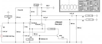
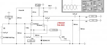
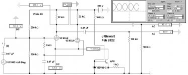
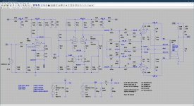
The E8 series sims test a possible alternative using a SS device as a constant current. The SS could be an NPN transistor or a FET. This sim is running an idealized NPN transistor. Whatever is selected needs to run at ~125V. Some people have used an MJE340 in the Mullard 520.
Some builders use 3-terminal regulators set in the CC mode. And still others like me use a long resister tail to -150V. And some simply set the plate resisters to ~10% different.
A simple vers takes current to drive the reference Zener from the cct cathodes. But that puts 100K in parallel with the CC device. A last cct derives Zener current from the 383V plate supply.
The SS tail provides a much better matched drive to the output tube grids. And a 3V signal at the input of this cct would drive the KT88 to full power.
On your last sim I see the voltage on the KT88 U2 to be +520V at the grid. And the plate -75V. Some simulators fail if there are too many parts to keep track of. U1 KT88 looks OK. That may be the cause of some of the results you are seeing.
The 8K tail sets the DC conditions correctly. But the drive voltages to the output stage are poorly matched. Clearly, another solution is needed.
In these Sims some of the scope traces are set at 100V/div while others are at 50V/div. All are DC connected so that the traces are offset by 300V so that they appear on screen.
The E8 series sims test a possible alternative using a SS device as a constant current. The SS could be an NPN transistor or a FET. This sim is running an idealized NPN transistor. Whatever is selected needs to run at ~125V. Some people have used an MJE340 in the Mullard 520.
Some builders use 3-terminal regulators set in the CC mode. And still others like me use a long resister tail to -150V. And some simply set the plate resisters to ~10% different.
A simple vers takes current to drive the reference Zener from the cct cathodes. But that puts 100K in parallel with the CC device. A last cct derives Zener current from the 383V plate supply.
The SS tail provides a much better matched drive to the output tube grids. And a 3V signal at the input of this cct would drive the KT88 to full power.
On your last sim I see the voltage on the KT88 U2 to be +520V at the grid. And the plate -75V. Some simulators fail if there are too many parts to keep track of. U1 KT88 looks OK. That may be the cause of some of the results you are seeing.
Attachments
-
 Proto E6 8K Tail No Signal.JPG54.6 KB · Views: 86
 -
 Proto E6 8K Tail.JPG56.5 KB · Views: 82
 -
 Proto E6 18K Tail No Signal.JPG55 KB · Views: 74
 -
 Proto E6 18K Tail.JPG54 KB · Views: 68
 -
 Proto E8 SS Tail 10V Drive.JPG59.3 KB · Views: 68
 -
 Proto E8 SS Tail 8V Drive.JPG57.8 KB · Views: 73
 -
 Proto E8 SS Tail 3V Drive.JPG58.4 KB · Views: 70
 -
 Proto E8 SS Tail 3V Drive Scope 50v per Div.JPG56.6 KB · Views: 71
 -
 Proto E8 SS Tail 3V Drive Scope 50v per Div Zener from HV.JPG60.6 KB · Views: 82
Check that there is no way the ground currents from the output stage can get back into the input stage. Note the speaker - transformer ground is taken to the wrong place through a wire R22. At low levels the PP nature of the output stage keeps current in R22 constant but at high levels there is lots of 2nd harmonic.
.png")
The SS tail Mr Steward has another advantage. I like DC coupling of the first stage to the LPT as it makes the LF stability better. However the ef86 plate operating voltage is very variable form device to device. Adding a CCS in the second stage prevents the LPT plate voltages being a function of the ef86 plate voltage.
The speaker return side of the OPT should be connected directly (and only) to the grounded side of R16. I use shielded cable for the NFB, and that’s the shield.Check that there is no way the ground currents from the output stage can get back into the input stage. Note the speaker - transformer ground is taken to the wrong place through a wire R22. At low levels the PP nature of the output stage keeps current in R22 constant but at high levels there is lots of 2nd harmonic.
Yep agreed.
Here's my silly idea of the day. Take some of the current in the cathode resistors and use this to pre-distort the driver signal. Using a current mirror CCS its easy to do.
.png")
Here's my silly idea of the day. Take some of the current in the cathode resistors and use this to pre-distort the driver signal. Using a current mirror CCS its easy to do.
Attachments
Last edited:
Ha! Nice idea! Tried that, see below schematics and measurements, doesn't seem to do much in reality?
Attachments

Yes, I actually use a continuous ground plane for the amplifier (not including the PSU obviously) and indeed hook the GND from the OPT directly to the grounded side of R16 via a shielded cable.The speaker return side of the OPT should be connected directly (and only) to the grounded side of R16. I use shielded cable for the NFB, and that’s the shield.
Yes, I'm going to try that next, expect an update today on how that worked out.The SS tail Mr Steward has another advantage. I like DC coupling of the first stage to the LPT as it makes the LF stability better. However the ef86 plate operating voltage is very variable form device to device. Adding a CCS in the second stage prevents the LPT plate voltages being a function of the ef86 plate voltage.
Another option is to use a gyrator as load for the EF86, this way you can fix the output voltage to DC couple first and second stage.
You read my mind! That's on my todo list for today! Any suggestions?Another option is to use a gyrator as load for the EF86, this way you can fix the output voltage to DC couple first and second stage.
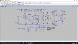
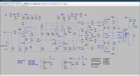
Okay, one thing I wanted to try and that's have the CCS also enforce balance by comparing the current through both anode resistors, please see attached schematic. The reasoning behind this is the following:
DC analysis
The two 220K resistors are equivalent to a single 110K resistance fed from the anodes of either section of the 6922.
AC analysis
If the two halves of the 6922 are perfectly balanced, one anode will be swinging more positive while the other is swinging more negative, and the combined AC voltage at the junction of the two 220k resistors will be zero, leaving only the DC component.
But when the two halves don't have identical Mu, and for example the input side has a higher gain than the feedback side of the pair, the voltage at the junction of the 220K resistors will be an AC signal, out of phase with the input signal. This causes an AC variation on the base voltage which in turn modulates the collector current in such a way as to place an AC signal on the cathodes in-phase with the input signal, of exactly the right amplitude to cancel out the excessive gain of the input side of the pair.
So consequently the AC balance of the LTP is now primarily dependent on the match of the two 220K resistors, and much less dependent on the intrinsic Mu or gain of each triode section. So now we have a self-balancing circuit without the need to balance the triode sections of the 6922, which also doubles as a very high impedance CCS and also a form of local feedback within this stage to improve balance.
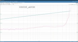
How does this fare in practice? I don't see a direct improvement in the THD measurement, see attached measurement results nicely combined in one easy to read screenshot. Actually the 036 results are the top curve, which shows a slight rise in THD. Am I thus delusional and doesn't the above reasoning how this should work hold ground? Or am I simply measuring the wrong metric?
DC analysis
The two 220K resistors are equivalent to a single 110K resistance fed from the anodes of either section of the 6922.
AC analysis
If the two halves of the 6922 are perfectly balanced, one anode will be swinging more positive while the other is swinging more negative, and the combined AC voltage at the junction of the two 220k resistors will be zero, leaving only the DC component.
But when the two halves don't have identical Mu, and for example the input side has a higher gain than the feedback side of the pair, the voltage at the junction of the 220K resistors will be an AC signal, out of phase with the input signal. This causes an AC variation on the base voltage which in turn modulates the collector current in such a way as to place an AC signal on the cathodes in-phase with the input signal, of exactly the right amplitude to cancel out the excessive gain of the input side of the pair.
So consequently the AC balance of the LTP is now primarily dependent on the match of the two 220K resistors, and much less dependent on the intrinsic Mu or gain of each triode section. So now we have a self-balancing circuit without the need to balance the triode sections of the 6922, which also doubles as a very high impedance CCS and also a form of local feedback within this stage to improve balance.
How does this fare in practice? I don't see a direct improvement in the THD measurement, see attached measurement results nicely combined in one easy to read screenshot. Actually the 036 results are the top curve, which shows a slight rise in THD. Am I thus delusional and doesn't the above reasoning how this should work hold ground? Or am I simply measuring the wrong metric?
Attachments
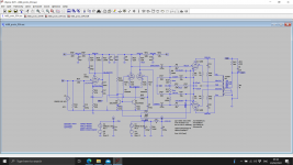
Alright, I tried the alternative, simplified LTP that John suggested and baudouin0 simulated. Unfortunately there's very little wiggle room, I'll explain why from the schematic and the THD vs. output power measurements, see attached. The voltages listed in the measurement are the voltages at the collector of Q1, a MJE340, as the KSC1845 wouldn't tolerate such high voltages. At voltages <138V the distortion is>5%, simply because there's not enough voltage between the grid and the cathode of the 6922, so the triode is simply not conducting. At voltages >142V the distortion starts to rise again, and the anodes of the 6922 sit at >350V which is a fair bit over the 300V maximum. An optimum seems to be around 138V. Take note that the calculated voltages in the schematic do not accurately reflect reality, that's why I've added voltages labeled with a *, these are the actual measured voltages.
Attachments

The AC balance of a CCS LPT is always good - as what goes up one plate does not go up the other - there is no where else for the current to go - does not depend on mu. Mu will affect gain however. The DC coupled approach does not actually save a coupling stage in the stability calculation - sorry. The other grid always tracks the first after a delay so the DC differential gain is zero - so its still the same as coupling the first stage to the LPT. I would make R1 R2 470R.
You can bias the grids right down to 0V with the current mirror as long as the worst case cathode AC voltage is enough to make the current mirror work. I think you are OK with E88CC.
I wonder if you would be better making your distortion measurements with the loop open. It should be easier to see whats occuring. You can make R39 and R40 quite small you only need about 300mV across them. This would get you current mirror down to <800mV on cathode. You could also bias the grids at say 10V if you need more headroom.
Last edited:
Sander, sorry to be late, but this caught my eye. To me that signifies that the distortion is not in the output stage. AC-removing the cathode resistors would increase output stage distortion but would also increase loop gain so the feedback can correct distortions anywhere in the loop.On that note, one thing that puzzled me is that decoupling the 10R kathode resistors for the KT88s reduced distortion across the board.
The fact that the result is lower distortion says that it originates before the output stage.
jan
I think there was some distortion cancelation occurring between the LPT and the output stage. I would agree with what you say and not fit them.

- Home
- Amplifiers
- Tubes / Valves
- KT88 PP - Dotting the Is, crossing the Ts