https://www.diyaudio.com/community/threads/el84-amp-baby-huey.72536/post-1498232Thanks! I’ll whip that up tomorrow and see whether I see an improvement on the prototype.
I just arrived back home, it’s quite late here, I will search something tomorrow.P.s. any suggestions for a gyrator load for the EF86 you mentioned earlier? I mean I can cobble something together, but if you have a proven design you’d like to share I’d rather hit the ground running.
Thanks! Have a good night!I just arrived back home, it’s quite late here, I will search something tomorrow.
Just you, I guess. Btw your product is just a show of what you can do, not that you would actually want to listen to a tube amp. Be happy with your Williams clone and especially the help others have given you. Without them, it would have died an early death.Nobody cares, least of all me.
Would it? No it wouldn’t! And may I suggest you refrain from making these kind of ad hominem posts unless you want your account suspended just like on the other forum where you kept harassing people.Just you, I guess. Btw your product is just a show of what you can do, not that you would actually want to listen to a tube amp. Be happy with your Williams clone and especially the help others have given you. Without them, it would have died an early death.
Not much progress today, just a few minor changes, for example we gained a transistor and a resistor in order to add a cascode to the current source. At this point I get the feeling every reduction of a mere fraction of a percent of distortion is something that I need to fight for, but as long as there's progress, although slow, I'll keep chugging along.
Attachments
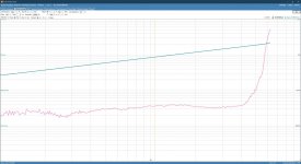

Yes, the cascode eats up a mere 1.5V from the available headroom which is not an issue.Care there you don't run out of volts on the CCS.
Yes I think its fine on the E88CC at full swing. For a 12AX7 I needed a slight negative supply on the CCS.
If there is a negative supply available for the CCS why not use it? Having a few volts of headroom might prevent you from hitting a hard voltage limit, but when VCE’s get small capacitances start getting nonlinear. Things stay very linear with 20 volts or more on it. And you can use an emitter resistor with a lot of voltage on it instead of only a few tenths. Makes everything better.
You could take the negative supply with a zener and put more voltage across the emitter resistors saving the cascode. You could even run the whole CCS of the raw negative supply and use a zener CCS. Swings and roundabouts again
Could do, I'll have a look, remember when I said I wanted to keep things simple 😉 ...If there is a negative supply available for the CCS why not use it? Having a few volts of headroom might prevent you from hitting a hard voltage limit, but when VCE’s get small capacitances start getting nonlinear. Things stay very linear with 20 volts or more on it. And you can use an emitter resistor with a lot of voltage on it instead of only a few tenths. Makes everything better.
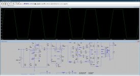
Could be even simpler - do away with the mirror and cascode if you bias the base with a 33 volt zener. With that much degeneration (39k emitter resistor) output resistance goes through the roof using one transistor.
P.s. I also tried a gyrator instead of the 100K anode resi
How's that? I'm with you on the 33V zener, but with a 39K emitter resistor I can't make it work, no matter how large the voltage on the negative supply.Could be even simpler - do away with the mirror and cascode if you bias the base with a 33 volt zener. With that much degeneration (39k emitter resistor) output resistance goes through the roof using one transistor.
Attachments
Oh, 8.2k for 4 mA. Don’t know how I got 39. Still orders of magnitude larger than the 6 ohms of intrinsic emitter resistance.
I tend to use a 6v8 zener returning the zener bias resistor back to 0V rather than HT. The transistor may need to dissipate more power or you can loose some in a collector resistor. Any old negative bias voltage will do its not fussy.
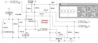
Here is another long tailed driver that fills the requirement to fully drive the PP KT88s.
The error others have often made to realize a proper solution has to do with failing to consult the plate curves for the 6DJ8 & put a load line on it.
Several have run much to small tail currents resulting in the 6DJ8 sitting up near the plate supply volts.
On this Sim we can see the plates are running at ~150V, a result of enough tail current.
There are several ways to get to a solution, this is simply one of them.
I've used this technique in the past, look up the threads where the 'Betty Crocker Special' is covered. Most often in a thread of Lingwendil
in his thread 'Flea powered Amp'. I got involved, it looked to me the P-P OPT impedance selected was not high enough.
So I covered PP versions of 6SN7. 6BL7, 6BX7 & 5998. The 5998 with a 280V supply managed an easy 10W in Class A.
Without exceeding its dissipation ratings. All that series of amps used various versions of the long tail.
I'm playing with a PP 6EA7/6EM7 these daze. It uses a 120K long tail to -150V. And 7W at clipping, a bookshelf amp.
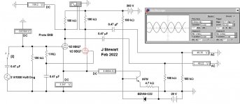
Do you have an objection to direct coupling to the input pentode? The removal of one LF rolloff from a NFB amp makes life a lot easier.
And we have seen a few posts back that it can be done successfully.
The error others have often made to realize a proper solution has to do with failing to consult the plate curves for the 6DJ8 & put a load line on it.
Several have run much to small tail currents resulting in the 6DJ8 sitting up near the plate supply volts.
On this Sim we can see the plates are running at ~150V, a result of enough tail current.
There are several ways to get to a solution, this is simply one of them.
I've used this technique in the past, look up the threads where the 'Betty Crocker Special' is covered. Most often in a thread of Lingwendil
in his thread 'Flea powered Amp'. I got involved, it looked to me the P-P OPT impedance selected was not high enough.
So I covered PP versions of 6SN7. 6BL7, 6BX7 & 5998. The 5998 with a 280V supply managed an easy 10W in Class A.
Without exceeding its dissipation ratings. All that series of amps used various versions of the long tail.
I'm playing with a PP 6EA7/6EM7 these daze. It uses a 120K long tail to -150V. And 7W at clipping, a bookshelf amp.
Do you have an objection to direct coupling to the input pentode? The removal of one LF rolloff from a NFB amp makes life a lot easier.
And we have seen a few posts back that it can be done successfully.
Attachments
Not a good idea, loading a high impedance pentode with a high impedance load.Another option is to use a gyrator as load for the EF86, this way you can fix the output voltage to DC couple first and second stage.
The operating point often become indeterminate, creating even more problems.
So the gyrator is OK with a triode. But not a pentode.
Just adds another level of complication.
Once you start using current sources for bias, and with sufficient voltage compliance, circuits tend to become “plug and play”. Becoming tube and transistor type-agnostic. Even when they’re direct coupled. Vgk doesn’t matter. You just get a change in gain, depending on the mu and rp. Add degeneration and it matters even less.
I just bought 40 6BQ7’s because they look like they show promise. More linear than 12AU7’s for gain blocks and decent enough as followers.
I just bought 40 6BQ7’s because they look like they show promise. More linear than 12AU7’s for gain blocks and decent enough as followers.
- Home
- Amplifiers
- Tubes / Valves
- KT88 PP - Dotting the Is, crossing the Ts