Thanks John, yes I am, work caught up with me the last few weeks though, but I plan to continue later this or early next week.Still spinning your wheels on that PP KT88 amplifier? Just curious.
Alright, time to dust off this project, here's where I am at, and I would've posted the much improved THD results if my audio analyzer didn't bite the dust. A new one is on its way from Texas, but won't be here until Thursday, so for now just a schematic to illustrate where I landed.
Attachments
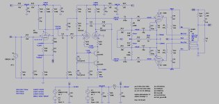
Cathode current is 120mA?
Plate is 485V (even a little higher than 485V on the screen).
Wow!
0.12A x 485V = 58.2 Watts total in the plate + screen; KT88 maimum spec is 46 Watts plate + screen.
You may get more power out, but at lower tube life. Red plating?
Really hot KT88 often draw g1 grid current, goes positive, thermal run-away.
I'm surprised that running the LTP biased so cold is the best choice. Operating point is way off to the right, where linearity is poorer and crowds the ability to swing signal output voltage positive. Maybe it works, but it's pretty surprising that it's optimum, especially for such a high Gm, high perveance valve.
All good fortune,
Chris
All good fortune,
Chris
SSassen, in another thread you showed a differential cascode LTP phase splitter. I actually built an amplifier like that and it works fine. Perhaps try this topology, at least in LTspice?
Cathode current is 120mA?
Plate is 485V (even a little higher than 485V on the screen).
Wow!
0.12A x 485V = 58.2 Watts total in the plate + screen; KT88 maimum spec is 46 Watts plate + screen.
You may get more power out, but at lower tube life. Red plating?
Really hot KT88 often draw g1 grid current, goes positive, thermal run-away.
Yes, they run a bit hot indeed, no red plating though. If I run them colder distortion is much, much higher?
SSassen, in another thread you showed a differential cascode LTP phase splitter. I actually built an amplifier like that and it works fine. Perhaps try this topology, at least in LTspice?
I abandoned that idea as the EF86 proved to be superior.
Looks good? It may be that you've got some distortion cancellation between the LPT and the output. If you change the LTP current/plate voltage you may be able to operate at lower KT88 current. If you drop the KT88 the distortion knee will move as that's when you enter class B rather than AB.
Last edited:
Not sure why you have C21 R38. The amp should be more stable with just a single dominate pole on the plate of the EF86.
Looks good? It may be that you've got some distortion cancellation between the LPT and the output. If you change the LTP current/plate voltage you may be able to operate at lower KT88 current. If you drop the KT88 the distortion knee will move as that's when you enter class B rather than AB.
Yes, I reduced to 60mA idle current with 525V B+, which gets me into the 70% max dissipation ballpark. C21 and R28 were needed to make it unconditionally stable the last time I tinkered with the prototype, I will certainly revisit and see whether they can be removed.
R22 is likely too big, causing you to effectively lose the dominant pole effect too soon. Open loop response needs to keep rolling off a little more before shelving it. There’s still as much gain there as a 100 mu triode, with just the 22k in the plate and 220 on the cathode - and even THAT typically needs compensation.
Sorry - meant R29 (The one in series with the dominant pole cap) It’s 22k and I had a brain fart.
- Home
- Amplifiers
- Tubes / Valves
- KT88 PP - Dotting the Is, crossing the Ts