Carlos,
I'm looking forward to your impressions of the amp with matched devices compared to unmatched. I'm having problems getting matched pairs from my stock!
I'm looking forward to your impressions of the amp with matched devices compared to unmatched. I'm having problems getting matched pairs from my stock!
Steve, in your latest 100watt schematic, C4 is connected to the wrong supply. You could ask the moderators to remove your ealier postings and put in a link to your latest corrected schematics.
Jaycee, your redrawn schematic in Eagle looks good and is in the more familiar form. Thanks.
Juma, what is your comment on C7? It looks fine in the latest schematics by Steve and Jaycee, or did I overlook something.
Steve, the offset control for the Voltage Gain stage is shown differently for the 50w and 100w versions. I thought the preferred one is what is shown in the 100w version. Could the 50w version also not be done in the same way? Thanks for your efforts and perseverance.
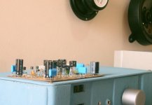
I am a little bit busy, so i will finish this amplifier in the next couple of days
I am adjusting speaker at same time and having visitors in my home.
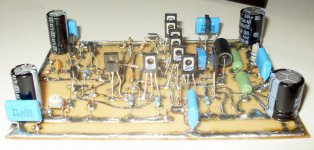
The transistors are matched.... some of them 1 percent tollerance.... maximum difference is 10 percent.
Even the output is matched.... NPN is 90 of gain and PNP is 96 of gain.
Yes...i could see one base is disconected from the board... the board not revised yet.
regards,
Carlos
[
I am adjusting speaker at same time and having visitors in my home.
The transistors are matched.... some of them 1 percent tollerance.... maximum difference is 10 percent.
Even the output is matched.... NPN is 90 of gain and PNP is 96 of gain.
Yes...i could see one base is disconected from the board... the board not revised yet.
regards,
Carlos
An externally hosted image should be here but it was not working when we last tested it.
[
It's the output devices I'm having the trouble with - 2SA1943's are in the hfe range 98 to 128, 2SC5200 in the range 61 to 83, so the closest match I have is 15%. I will be looking through another 12 but the ranges seem way off between PNP & NPN.
15 percent match is fine!
In special to output device... this is my opinion...let's listen Dunlap about this subject.
What do you think Steve?
Do you think matching is important into the output?
If the answer was positive, please explain why.
Carlos
In special to output device... this is my opinion...let's listen Dunlap about this subject.
What do you think Steve?
Do you think matching is important into the output?
If the answer was positive, please explain why.
Carlos
I will also be using these devices as drivers! 15% is for just 1 pair - next best is 102(PNP) to 83(NPN) = ~20%
The bias transistors I have are 2SA968A & 2SC2238A(NPN) with range 182-192 & 150-160(NPN).
I'm removing all these trannies from an existing Samson 550 amp of which I have 3 reclaimed from a recycling centre. Each amp has 6 PNP output trannies & 6 NPN devices along with 2*2SA968A & 2*2SC2238A devices. (Carlos, you are not the only destroyer on the forum 🙂)
So I will de-solder & test some more if it's worth continuing!
I guess another question I have is now that there is a pot for setting bias & a pot for setting offset both on the output stage - how important is trannie matching even for the bias pairs?
Samuel Jayaraj said:Steve, in your latest 100watt schematic, C4 is connected to the wrong supply. You could ask the moderators to remove your ealier postings and put in a link to your latest corrected schematics.
Jaycee, your redrawn schematic in Eagle looks good and is in the more familiar form. Thanks.
Juma, what is your comment on C7? It looks fine in the latest schematics by Steve and Jaycee, or did I overlook something.
Steve, the offset control for the Voltage Gain stage is shown differently for the 50w and 100w versions. I thought the preferred one is what is shown in the 100w version. Could the 50w version also not be done in the same way? Thanks for your efforts and perseverance.
C4 should attach to the other end of D12. The cap is correct on the board and should present no problem for the people that bought boards. When I stop making corrections every other day I will ask the moderators to do as you suggest. I still make a lot of simple (stupid) mistakes when doing the drawings. Try using a mouse without hands sometime.
The offset control shown in the 100W version will work in the 50W also. I did the 50W the way I did because there is no place on the boards I am selling at this time for this method. It can be done, but will require cutting a trace and adding the two resistors and trim pots on the bottom of the board. What I have shown for the 50W is much easier to do because there is already a location for the resistor and adding the trimmer in parallel is very straight forward.
Re: 15 percent match is fine!
First let me apologize for not replying sooner. My internet has been out for a couple of days.
I like to use matched transistors anywhere they are used in parallel or as a complementary pair. It improves measured distortion and reduces offset before adjustment.
jkeny:
What brand of transistors are you using? I find that with the Toshiba, matching is very easy within 5% even between NPN and PNP devices. I am using new transistors however, not salvaged. When you buy 500 at a time of each transistor it is easier to get matches.
destroyer X said:
In special to output device... this is my opinion...let's listen Dunlap about this subject.
What do you think Steve?
Do you think matching is important into the output?
If the answer was positive, please explain why.
Carlos
First let me apologize for not replying sooner. My internet has been out for a couple of days.
I like to use matched transistors anywhere they are used in parallel or as a complementary pair. It improves measured distortion and reduces offset before adjustment.
jkeny:
What brand of transistors are you using? I find that with the Toshiba, matching is very easy within 5% even between NPN and PNP devices. I am using new transistors however, not salvaged. When you buy 500 at a time of each transistor it is easier to get matches.
jkeny said:I guess another question I have is now that there is a pot for setting bias & a pot for setting offset both on the output stage - how important is trannie matching even for the bias pairs?
The method I show for setting offset has little influence on the transistor matching. I used this method in some of my more sophisticated amps because it can be done with a servo and without effecting the sound or low frequency bandwidth. I will show how I do that at some point as I show what this amp evolved into.
Steve,
I thought having R32 & R33 1K pots for setting the offset loosened the need for close matching on the bias transistors - is this wrong?
My transistors are all genuine Toshibas taken from an existing Samson 550. I de-soldered some more but no closer matches.
I thought having R32 & R33 1K pots for setting the offset loosened the need for close matching on the bias transistors - is this wrong?
My transistors are all genuine Toshibas taken from an existing Samson 550. I de-soldered some more but no closer matches.
jkeny said:Steve,
I thought having R32 & R33 1K pots for setting the offset loosened the need for close matching on the bias transistors - is this wrong?
My transistors are all genuine Toshibas taken from an existing Samson 550. I de-soldered some more but no closer matches.
These balance the current through the output stage. I still prefer to use matched transistors as I run the output stage open loop. Maybe this is a leftover from when I built very high power amps with many outputs. You can achieve very good sound without matching. I've never had trouble matching, so I still do it.
I know someone is going to ask. I don't use a multimeter for matching. I have a curve tracer and a dedicated transistor tester that both give very similar results. The upper limit of my test capability is limited to 200V at 2A. The lower range is 50V at 4A. This works for most transistors in an audio amp.
Hi Steve
After all these discussions about burning in components, for several hundred hours to make them stabilize and to do their best.
How about these narrow maching of transistors?
Are they never drifting away in any aspect, after months or years of duty in the amplifier?
The first messured narrow matching consists?
regards
Health problems forces me to stop construction...i cannot be sitted for too long
circulation problems...the left foot turns enormous because of return blood circulation damaged...also blood pressure is dangerous.
Sorry folks..will stop for some monthes till the health goes into a better shape.
bye
Carlos
circulation problems...the left foot turns enormous because of return blood circulation damaged...also blood pressure is dangerous.
Sorry folks..will stop for some monthes till the health goes into a better shape.
bye
Carlos
Attachments

Ragnwald said:Hi Steve
After all these discussions about burning in components, for several hundred hours to make them stabilize and to do their best.
How about these narrow maching of transistors?
Are they never drifting away in any aspect, after months or years of duty in the amplifier?
The first messured narrow matching consists?
regards
I don't worry to much about component drift if good parts are used to begin with. IF the transistors changed in gain it should show up as increased distortion and offset. That has not been the case in the units I have retested after years of use.
Sorry to hear that Carlos - I was looking forward to your report - take a rest & look after yourself - audio is not as important as your health.
I had a back problem in September (no audio building) & just recovered before Christmas so with time healing can take place.
I had a back problem in September (no audio building) & just recovered before Christmas so with time healing can take place.
Re: Health problems forces me to stop construction...i cannot be sitted for too long
Yes, take care of Yourself Carlos. I have no doubt You enjoy what You are doing, but maybe it's time to relax with friends and family instead.
Remember, You should hopefully last many years to come, so please look after Yourself.
All the best
Ebbe
destroyer X said:
circulation problems...the left foot turns enormous because of return blood circulation damaged...also blood pressure is dangerous.
Sorry folks..will stop for some monthes till the health goes into a better shape.
bye
Carlos
Yes, take care of Yourself Carlos. I have no doubt You enjoy what You are doing, but maybe it's time to relax with friends and family instead.
Remember, You should hopefully last many years to come, so please look after Yourself.
All the best
Ebbe
- Status
- Not open for further replies.
- Home
- Amplifiers
- Solid State
- Krill - The little amp that might...