


Congratulations Phil - Thanks for the update! 😀
Looks pretty good for a bunch of test clips!
You must have read the post where Steve D said that he just tossed everything onto a board and it came out sounding pretty good.
The last of the parts for my 50W's should get here around this coming Monday so I hope to have something to report next week.
Buuuutttt just in case - I'll have a little red jug handy!!
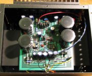
Attachments
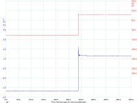
The input filter seems to have cleaned up the 10kHz square cf the 1kHz square.
What value have you set?
Hopefully S.D. will give us some hints on where to apply compensation and the best signals/loads to help determine what that compensation should be.
What value have you set?
Hopefully S.D. will give us some hints on where to apply compensation and the best signals/loads to help determine what that compensation should be.
originally posted by c2cthomas
Buuuutttt just in case - I'll have a little red jug handy!!
And here I thought you meant this little red jug, although I believe this is flammable.
Attachments
Hello Andrew
For the sake of a common schematic, I'm referring to the 50w schematic posted by Steve in post#1460 of the "Krill - The little amp that might..." thread:
http://www.diyaudio.com/forums/showthread.php?postid=1784709#post1784709
I've pasted that same schematic below.
My circuit is essentially the same. I use R1=1K, C2=220pF. My system has no caps in the signal path from stylus to speakers so I want to minimize the input offset. I also use a 2SC3381 for the input differential.
The Krill boards use a cap from the collectors of Q4/Q6 back to the collector of Q1 for compensation. The first results I posted used about 10pF. The recent results use 56pF which I think will get reduced as I clean up my work. The prototype is a rat's nest of wires. And I've been away from the bench for a few years and slapping my forehead a lot after I overlook something that would have been obvious before.
Phil
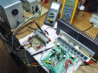
Attachments
PH104 said:
I've been away from the bench for a few years and slapping my forehead a lot after I overlook something that would have been obvious before.
Phil
Dr. Phil =
Me =


I hope you are joking.PH104 said:The Krill boards use a cap from the collectors of Q4/Q6 back to the collector of Q1 for compensation.
That is a Miller comp cap.
I found this circuit theoretically attractive because it did not need a Miller comp cap as proposed by S.D.
I also thought the absence of a Miller comp cap was part of the reasoning that made this amp nice to listen to.
PH104 said:
The Krill boards use a cap from the collectors of Q4/Q6 back to the collector of Q1 for compensation. The first results I posted used about 10pF. The recent results use 56pF which I think will get reduced as I clean up my work. The prototype is a rat's nest of wires. And I've been away from the bench for a few years and slapping my forehead a lot after I overlook something that would have been obvious before.
Phil
Hi Phil,
That sound's like C2 that you are talking about - SD stated that this cap could be used to cancel oscillations IF it was needed - and that in most cases it should not be required. I'm not to questioning your construction efforts - simply trying to give you some constructive input (no pun intended). 😉
Perhaps when you get the prototype rats nest put in order you will find that this capacitor is no longer required.
Not a joke. I do admit to describing it in an odd way as I was describing it from memory of the board layout without looking at the schematic.
There's some evidence that says that cap will either go away or can become very small with the power supply correctly implemented on the board and the circuit tweaked up a bit. There might be an advantage to using a small, high-quality cap to firmly establish the dominant pole, at least as far as stability goes. As it's Steve's circuit, I'll leave further comments to him. But in my prototype, the Miller compensation cap wasn't necessary with only two pairs of o/p transistors; it was only after I started adding more o/p pairs that I got a little peaking on the square wave. Some extra bypassing helped a lot. But I'm not spending more time on that now as I'm not sure what the final amp will look like. I'm working on that and hope to post something later.
There's some evidence that says that cap will either go away or can become very small with the power supply correctly implemented on the board and the circuit tweaked up a bit. There might be an advantage to using a small, high-quality cap to firmly establish the dominant pole, at least as far as stability goes. As it's Steve's circuit, I'll leave further comments to him. But in my prototype, the Miller compensation cap wasn't necessary with only two pairs of o/p transistors; it was only after I started adding more o/p pairs that I got a little peaking on the square wave. Some extra bypassing helped a lot. But I'm not spending more time on that now as I'm not sure what the final amp will look like. I'm working on that and hope to post something later.
Hey Thomas -- C2 on the board is the one. Thanks. And no offense taken - I know where you're coming from.
I've successfully used different values of C2 from 0 to 100 pF depending on the configuration I was playing with. The final value might even be selected by listening. There was a thread on this a few weeks ago, not sure where it's at. I think AKSA was one of the contributors. I couldn't find it with a quick look. Will check for it later.
But....... there is a Krill picture from the other thread that shows the C2 cap (circled in red), which makes sense for an amp intended for commercial sales.
Attachments
Borbely/Krill
I am now using a Borbely voltage gain stage with the Krill output stage. The Borbely VGS is very close to the schematic posted at:
http://www.borbelyaudio.com/home_theater.asp
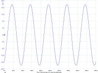
I am running it at +/- 70 VDC fully-regulated with a discrete series regulator. The Krill o/p stage is operating from a separate high-current supply at +/-63 VDC. At 10W into 8 ohm load, the output is -3 dB down at about 400 kHz relative to 1 kHz reference.
Scope pictures soon.
I am now using a Borbely voltage gain stage with the Krill output stage. The Borbely VGS is very close to the schematic posted at:
http://www.borbelyaudio.com/home_theater.asp
I am running it at +/- 70 VDC fully-regulated with a discrete series regulator. The Krill o/p stage is operating from a separate high-current supply at +/-63 VDC. At 10W into 8 ohm load, the output is -3 dB down at about 400 kHz relative to 1 kHz reference.
Scope pictures soon.
Attachments
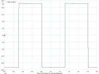
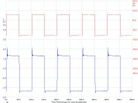
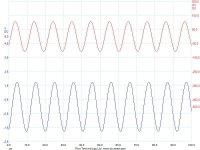
10 kHz square, 8 ohm load
EB/Krill
Top trace is input, lower output with 10x probe. The cycle or two of ringing is most likely an artifact of the setup. There was some oscillation when connecting the Borbely front end to the Krill o/p. The solution was a 4.7k isolation resistor between the two stages.
EB/Krill
Top trace is input, lower output with 10x probe. The cycle or two of ringing is most likely an artifact of the setup. There was some oscillation when connecting the Borbely front end to the Krill o/p. The solution was a 4.7k isolation resistor between the two stages.
Attachments

The Borbely DC-150/Krill combination is the one I will build for listening. I'm currently using 2 modified Parasound HCA-3500 amps, each one bi-amping a Mirage M-1si speaker. So I'll build two stereo EB-Krills at 160W per channel. I have the Borbeley stages already built and the Krill o/p stages are simple to build so hopefully it won't take long.
It looks like the krill amplifier is a winner for all the intents and purposes.
I've been thinking in building it but I lack the layout of the 100 W version and no matter how hard I search on both threads I can't find it.
Any of the good souls who write on these threads could point me out
with a link or else to where this layout was published?
I'd appreciate.
I've been thinking in building it but I lack the layout of the 100 W version and no matter how hard I search on both threads I can't find it.
Any of the good souls who write on these threads could point me out
with a link or else to where this layout was published?
I'd appreciate.
- Home
- Amplifiers
- Solid State
- Krill construction thread - 100W version