Indeed a nice looking board.
By looking at it you answered one of my future questions. I also had the intention of replacing the two back to back electrolytics of 1000µF/16V by a single 1000µF Black Gate non polar.
Regards
By looking at it you answered one of my future questions. I also had the intention of replacing the two back to back electrolytics of 1000µF/16V by a single 1000µF Black Gate non polar.
Regards
Hi,
the back to back 1000uF+1000uF 16V have an effective capacitance of 500uF 16V.
You can substitute a bipolar 470uF 25V or even 40V for near identical bass performance.
You may find that a bipolar 220uF 100V performs sufficiently well in the bass with that film bypass cap to assist the extreme treble.
The advantage of 100V cap is that diode protection is not required, but may still be an advantage to save the input transistors.
BTW, F-3db for 1mF+1mF =0.38Hz
470uF F-3db=0.41Hz
220uF F-3db=0.88Hz.
Will we be able the hear the changes between these options?
Has anyone tried alternative NFB caps yet?
or going to DC servo and fully DC coupled (input & NFB).
I simply used the 1000uF because IIRC it was cheaper than the 470uF ;-)
In theory in an ideal world one can bypass the NFB cap without the servo, but don't come complaining if something blows up
In theory in an ideal world one can bypass the NFB cap without the servo, but don't come complaining if something blows up
Well, I have both the 470 and 1000µF laying around. Yet another thing to tinker about!
Regards
Regards
First Krell PCB completed.
Hi
I am very impressed with the work Pierre has done on this project. The finished product looks simple but it has consumed more time that meets the eye.
It will be interesting to see if there are any difference in the sonic character of this board versus a board assembled with ordinary run of the mill components ?
I have a niggling suspicion that one of the main reasons why the KSA50 was so popular was the fact that it had very short wirelengths between the PCB and the main output devices. I would not therefore not be surprised if the wiring layout is possibly more crucial than the actual quality of the board components. If so it could have drastic implications on the preferred heatsinks one should use with this project.
Jozua
Good move!GeWa said:Indeed a nice looking board.
By looking at it you answered one of my future questions. I also had the intention of replacing the two back to back electrolytics of 1000µF/16V by a single 1000µF Black Gate non polar.
Regards
😎
Here's some voltage's on mine so far
Board only, no output's
25v (+-) for device safety check
I'm using,
Q 1-4 2s#2240/970 GR hfe 320 all
Q 9-12 2sa968/C2238 Toshiba's
Q 5-8 ZVx2110A
Drivers, same as BOM
No cpx caps yet, except cp11/12 (.47uf Wima MKP10)
At 25v (+-) rail (across resistor) Star grd. the 1st or 2nd pad next to the sig. entry (note: silkscreened side cpx caps GND not connected)
R7= 2.1v R9 = 2.14v R 22= 1.37v R28= 1.39v
R8= 2.1v R10= 2.15v R 23 = 1.26v R29= 1.26v
These should be close when bringing up on a Varaic- if not then you have Q1-4 in the wrong location's like this DA did..,..
R38-41 adjust VR2 to 1.0v for now
C7= 3.1v
Full rail voltage (1 monoblock)
Avel 800va 40+40
AC 117v = 59v unloaded
TO-3 MJ15024/25 outputs
Bias set for .250v (for now) across any 1 emitter (.47ohm)
PNP (4) 11mv +/- NPN (4) 26mv +-
54.4v loaded at (.250v ) bias level
R7-10 all 7.65v
R22=1.2v R28= 1.3v
R23=1.18v R29= 1.18
R38-41= .900v all (at .250v bias)
Output dc= less than 1/2 a MV wander
Heat sink temp- Each measure 8"x 8 1/2"x 3" (4 TO3 outputs) on each is 58C (bias .250v) without fan
At full bias (.580v+) these will have to fan cooled for sure.
No issues yet (3hours running) 🙂
Regards
David
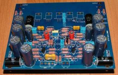
PWatts said:OK here it is, a fully populated PCB... there are 5 Black Gates, 6 Panasonic FC, 2 Mundorf, 1 teflon-film and a motherload of Riken resistors per board.. and of course blue LED's 😀
Damn, & I thought PRP, IRC and Holco resistors were expensive! Good job on the board! 😎 Save those gold plated cut off leads for use as jumpers on other projects?
Is that the heat sink that was selling on eBay? The ones Mark G. pointed out? BTW, I still need to get the heat sinks for this board . I will keep looking on eBay but if you have a North American source could you please point me?
I feel sort of jealous. I have run out of space and time to continue with the amp building. However, on a good note I am trying to cut a deal on renting a work-shop studio in an old factory warehouse here in the city. The building currently has at least one recording studio and one carpentry shop already set up and doing biz. 🙂 If I get the space then I should be able to get back in the grove full throtle.
Get your kicks,
Shawn.
Mark, Mark...where art thou Mark?
Please ship my boards and diodes ASAP as I want to start building.
Please ship my boards and diodes ASAP as I want to start building.
When I last hear from Mark about 10days ago he said he's out of town for work but should be back in "a few weeks" and that he would ship out the boards the moment he gets back.
The heatsinks were the result of many hours spent on an old salvaged heatsink with a CNC mill by removing fins etc. Turned out quite nice. The predriver sinks were also milled from old 3mm aluminium stock and anodized dark grey.
NB: For those not familiarized with the Pinkmouse KSA50 klone, remember to join the power and signal ground when initially testing.. leaving out the power ground is ok, but to only connect it and not the signal ground is another thing
I should be home by the end of next week to finish up the last of the shipping. I am still stuck at work in Wyoming.
The driver heatsink can actually be done by hand fairly easily with a hacksaw and medium bastardfile. Of course a mill is prefered... I did mine on the mill but wouldn't hesitate to do them by hand with no acces to a mill. If no one else does it before me I will post a "how to" so everyone can make them up.
I have to laugh at who ever runs this site and how its set up! The fact that the technical name of a file gets blotted out... so I'll spell it backwards for everyone...
DRATSAB
Mark
AndrewT said:Hi Pink,
any chance you could persuade the Forum to relax the application of the dictionary?
why ?
just say Drek and evrthng is fine 😉
- Home
- Amplifiers
- Solid State
- Krell KSA 100mkII Clone