Well spotted Q,
would it be even better with air sleeving or vacuum sleeving for best of all.
How much would they charge us to buy those options?
would it be even better with air sleeving or vacuum sleeving for best of all.
How much would they charge us to buy those options?
QSerraTico_Tico said:serious
Sound ? A guy can't pimp his amp ?

Why do you think we Yanked THESE guys out ? Sure glad i don't have that accent. (my favorite Yankovic clip)
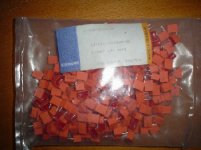
I just love teflon, to calm you down here's a couple of the best/most accurate teflon caps ever made. =>=>=>
www.thel-audioworld.de/bauteile/kp1/kp1.htm
www.eio.com/public/capacitr/0208.html
Attachments
Hi Crypt0wind I would be interested in the two boards you have please contact me
F.A.O. Mark I have still not recieved the boards or diodes, and cannot seem to contact you through email, can you tell me when they shipped? You also mentioned that you would send me some close up photos and PDF file to help with my assembly,
tnx Andrew...
F.A.O. Mark I have still not recieved the boards or diodes, and cannot seem to contact you through email, can you tell me when they shipped? You also mentioned that you would send me some close up photos and PDF file to help with my assembly,
tnx Andrew...
Has anybody started building ?
Gentlemen
I just wondering has anybody started building or is there still a lot of people waiting for parts?
All this talk of downscaling output seems to suggest that we have a common problem of finding suitable heatsinks ?
At this rate it looks if very few of these amps are going to be completed.
Jozua
Jozua said:started
Mmm , think i posted yesterday that i've started.
~160 Dale resistors just came in, i'm on the roll.
I seem to have all the hardware, minus the 1N5309 CRDs.
the teflon sleeving is serious, it requires a medical/watchmaker magnafying glass/light to get the resistor leads in the sleeve. The sleeves and stand-offs make the soldering easier, peek some pictures of older Mark Levinson gear or big buck Japanese amps.
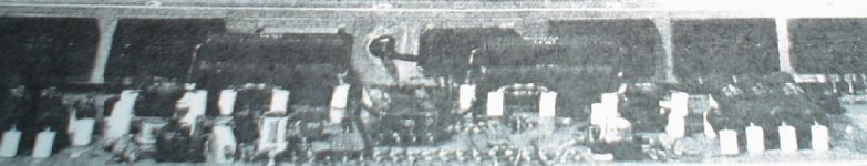
Here's a pic of an IKEA beaded Burmester power amp board, Toshiba RET 2SA1095/2SC2565 drivers and triple Sanken RET 2SA1216/2SC2922 output stage. Twice the MSRP of a KSA100.
(B&W pics allow for a decent picture size on a file size limit of 60Kb ! )
[ps :i'm so sloppy, did i ever mention i'm an ace of finite elements modelling for vibration analysis ? PEEP ,second line]
Attachments
Well jacco, it seems like it's you and me on the race. Mine's almost done though, only got to match&mount the drivers and it's all systems go. That's for two standard boards, and two others where the zeners are left out with an active regulator for the LTP and front-end are not far behind.
Hi,
I have to drill and tap heatsinks, match the outputs and start assembling
First PCB is almost there, but missing 62pF base to collector caps.
Are the values critical? I have 47pF & 100pF.
Do they work as Miller comp caps?
How did Krell wire up the NFB from the outputs to the driver board?
The twin connections (labelled output) seem to be waiting for two wires from the output stage, but where from exactly. I want to copy the Krell scheme before I do any other NFB changes.
Do the 1n5309 current have a negative temp coefficient?
I have just matched up another type and found that current falls as voltage rises (3.2mA@5V, 3mA@29V). It is a temperature thing. Wrapping my fingers around the tested diode raises and stabilises the current by cooling the glass package. The current returns to it's lower level and then hunts (+-0.5% in 15Seconds or so) as air wafts over the device.
No idea about the current diodes I'm afraid, anyone else?
The Miller caps should work fine with 47pF or 100pF, I doubt if it would make an audible difference. Going on memory, many people used different values on the KSA50 without problem. Easiest would be to check the 10kHz squarewave response with both values, smaller may ring a bit, larger will round it off slightly. Otherwise go for 33pF and another one tack-soldered on the bottom; you'll have to do that with the 20pF cap as well anyway.
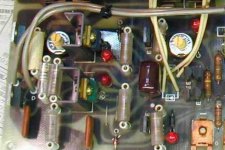
The NFB was wired as follows: The boards were mounted on the heat tunnels, with four NPN's on the left and PNP's on the right. The TO-3's were mounted along with their emitter resistors on small PCB's, and the back pair's wires were simply passed through the front pair, with each pair having its own base wire. The cable lengths were therefore not nearly the same. They were wired into the boards exactly as mine are, with the output the large fat trace at the top connecting the two pads. The speaker output was taken at the front pair of the NPN for the left channel and PNP for the right (to keep it at the chassis's edge), so the length of the transistors to the speaker terminals also differed by over 20cm from the opposite back pair.
You can therefore say that the NFB joint is on the boards in the top centre, and the path is (for the left channel) NPN back pair, NPN front pair+spk out, board, PNP front pair, PNP back pair. For the right it's NPN back pair, NPN front pair, board, PNP front pair+spk out, PNP back pair.
In conclusion, a pretty horrid scheme so you're likely to only improve on that. With faster transistors e.g. MJL4281/4302 it will perhaps not work too well though.
The Miller caps should work fine with 47pF or 100pF, I doubt if it would make an audible difference. Going on memory, many people used different values on the KSA50 without problem. Easiest would be to check the 10kHz squarewave response with both values, smaller may ring a bit, larger will round it off slightly. Otherwise go for 33pF and another one tack-soldered on the bottom; you'll have to do that with the 20pF cap as well anyway.
The NFB was wired as follows: The boards were mounted on the heat tunnels, with four NPN's on the left and PNP's on the right. The TO-3's were mounted along with their emitter resistors on small PCB's, and the back pair's wires were simply passed through the front pair, with each pair having its own base wire. The cable lengths were therefore not nearly the same. They were wired into the boards exactly as mine are, with the output the large fat trace at the top connecting the two pads. The speaker output was taken at the front pair of the NPN for the left channel and PNP for the right (to keep it at the chassis's edge), so the length of the transistors to the speaker terminals also differed by over 20cm from the opposite back pair.
You can therefore say that the NFB joint is on the boards in the top centre, and the path is (for the left channel) NPN back pair, NPN front pair+spk out, board, PNP front pair, PNP back pair. For the right it's NPN back pair, NPN front pair, board, PNP front pair+spk out, PNP back pair.
In conclusion, a pretty horrid scheme so you're likely to only improve on that. With faster transistors e.g. MJL4281/4302 it will perhaps not work too well though.
jacco vermeulen said:datasheet: nominal around - 0.3 % current change for each degree difference from 25C.
More delta-T teflon sleeves=>
Isn't that why the military uses the coated Dales? Something about the coating helping with thermal and vibrational stability. (?)
... and there was life 😀
Just soldered up the last few components on one board and fired her up (sans output stage), all systems go from the very beginning. Will try to post a pic tonight, and if all goes to plan have the full amp going by the weekend.
Mark has emailed and apologized for the delay, he's out of town for a couple of weeks but vowed to ship out the remainder of the boards&diodes the moment he gets home.
AndrewT said:Hi,
I
First PCB is almost there, but missing 62pF base to collector caps.
Are the values critical? I have 47pF & 100pF.
Do they work as Miller comp caps?
Andrew, send a PM, (with your adress) and I can ship a couple of Mica´s 62pf (matched if you want).
Regarding "my" KSA100 project, all 6 boards almost nearly finished, only problem now is that I hadnt received any decent answer from Mouser regarding a price quotation for a driver heat sink. First answer was a message that informed me those sinks was available in Europe only !!?? (my location is Europe) When sending a new question I received a quotation for 500 pcs (I was asking of 6 pcs)..........Should I cry or laugh, 😀

😎
I didn't even bother to try a commercial driver sink and milled them by a small CNC machine I managed to have.. if it wasn't that it took almost 40hours to do four driver and predriver sinks from the originals old sinks I started off with I'd have suggested a "group manufacture" ;-) Fortunately they look great and fit like a glove.
Hi Flod,
thanks for the offer.
Depending on the answer to the following question I may/not take you up on that.
When KSA100mk2 is set up with faster drivers and output devices, will this have a bearing on the minimum value of Miller comp cap fitted for C5 & 6?
Or
Will the combination of faster devices and reduced VAS feedback cause even bigger stability issues (=less phase margin)?
I'm trying 47pF NP0 just to get me started and then replacing with a more suitable cap once testing proves which value seems about right.
Heatsinks
Flodstroem
I think we need to explore the possibility of a group buy for predriver and output device heatsinks.
For me there it is important to remain as close as possible to a professional look. If this amp sounds as good or better as the original it might be worth it to do a proper job. I cannot imagine these boards cluttered with improvised junk heatsinks - in fact one quickly looses respect for such a project.
It also a pleasure working with the correct heatsinks.
The board design looks good, the boards themselves are better than the originals with a strong possibility that most of us are going to use better components that what was available 20 years ago.
Let not mess up a potential reference project with some backstreet enclosure or DIY heatsinks.
Is there anybody who can assist with a possible groupbuy ?We basically need someone with the correct connections.
Jozua
troystg said:
Isn't that why the military uses the coated Dales? Something about the coating helping with thermal and vibrational stability. (?)
Jaccovity is just teasing ya all.......
even if he's going to use that ptfe sleeving, I can bet that will be from
" I will just because I can,not because I must or is it better " sort of approach............
AndrewT said:Hi Flod,
thanks for the offer.
Depending on the answer to the following question I may/not take you up on that.
When KSA100mk2 is set up with faster drivers and output devices, will this have a bearing on the minimum value of Miller comp cap fitted for C5 & 6?
Or
Will the combination of faster devices and reduced VAS feedback cause even bigger stability issues (=less phase margin)?
I'm trying 47pF NP0 just to get me started and then replacing with a more suitable cap once testing proves which value seems about right.
Ok Andrew, I think your last idea trying a 47pF NPO etc. sounds good, but if you need the Mica´s, just give me a hint.
Jozua, Regardind heat sink for the drivers, as I said in post #1480, I will use a professional heat sink, AAVID # 0S499 ( 3" of, in black, 1.2-1.3°C/W) for my 3 pair of drivers (approx. 15W total dissipation). That is the heat sink Mouser didnt yet offered me.
regards😎
To get this thread going again, it was already on page 4 go figure.
I got my mind set now to go with the BC546C for Q1, Q2 and BC556C for Q3, Q4. The problem is that I can't decide what to use for Q5, Q6 and Q7, Q8. I have all the parts for the three combinations but I just don't know which one to take.
ZVN2110A / ZVP2110A
ZVN2110G / ZVP2110G
IRFD110 / IRFD9110
Can somebody point me in a good direction please.
Regards
Take your pick ;-)
Personally I'd go for the G ones, the SMD pads with vias add some nice heatsinking capabilities. If you're scared of blowing the FET's for whatever reason, you can use the IRFD's in DIP-4 sockets though.
Personally I'd go for the G ones, the SMD pads with vias add some nice heatsinking capabilities. If you're scared of blowing the FET's for whatever reason, you can use the IRFD's in DIP-4 sockets though.
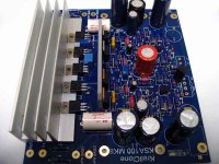
OK here it is, a fully populated PCB. It's safe to assume that this is the most exotic Krell ever component-wise, those who know Parts Connexion's catalogue may recognise most of them - suffice to say there are 5 Black Gates, 6 Panasonic FC, 2 Mundorf, 1 teflon-film and a motherload of Riken resistors per board.. and of course blue LED's 😀
Attachments
- Home
- Amplifiers
- Solid State
- Krell KSA 100mkII Clone