Hi,
Q9 & Q10 run hot.
I have slightly low voltage on the rails (+-48Vdc) and just 770mW being dissipated.
I fitted 20C/W clip on sinks and delta Ts is about 30Cdeg indicating that the advertised 20C/W is nearer double that.
I am going to remount these two transistors on the reverse side to give more room for a larger sink to dissipate 900mW with a delta Ts of about 20Cdeg resulting in Tj of about 50degC. They are just too far away from the driver sink to bolt on there.
BTW,
separate sinks do not need an isolator between transistor and sink and allow better dissipation. A combined sink requires an electrical isolator and increases Tc & Tj noticeably. But choose whichever meets your requirements.
I found that Q5&6 Vgs Nchannel is about 1.7Vgs @ 1.5mA and Q7&8 Pchannel is 3Vgs @ 1.5mA resulting in slightly lower voltage across D6 (28.4V) compared to D5 (29.8V). This difference between N & P is confirmed in the datasheet. I matched Vgs at Id=1.5mA rather than Idss.
Hi GeWa,
Looking nice! However, those two small Black Gate NX's are completely overkill in that application. But hey, at least they look good 😎 BG NX's are also designed to be used without bypassing, so I'd take out the film bypass cap if I were you.
Looking nice! However, those two small Black Gate NX's are completely overkill in that application. But hey, at least they look good 😎 BG NX's are also designed to be used without bypassing, so I'd take out the film bypass cap if I were you.
I've warned about Q9 & Q10 before, they dissipate quite a lot of heat and definitely require sinking.
Q11 & Q12 dissipate almost nothing and can be left unsinked. Don't know why Krell used the same heatsink for all four of these on the original besides conformity.
Q11 & Q12 dissipate almost nothing and can be left unsinked. Don't know why Krell used the same heatsink for all four of these on the original besides conformity.
Hello all... I am finally back home from my month long service trip in Wyoming. I worked alot and ate alot of good food!
Anyway I will resume shipping diodes and boards out this week starting Tuesday. So look for them over seas in about 10 days from this Tuesday or there abouts. Domestic will take much less time. Thanks for everyones patience while I've been out of town!!
Mark
Anyway I will resume shipping diodes and boards out this week starting Tuesday. So look for them over seas in about 10 days from this Tuesday or there abouts. Domestic will take much less time. Thanks for everyones patience while I've been out of town!!
Mark
Any amps playing yet?
Hi
I just wondering has anybody reached a stage where they can start auditioning the amp?
Compared to the KSA50 thread this one is very quiet. Do I sense a loss of interest or is everybody still struggling collecting parts or stuck on exploring enclosure options?
Jozua
Hi
I just wondering has anybody reached a stage where they can start auditioning the amp?
Compared to the KSA50 thread this one is very quiet. Do I sense a loss of interest or is everybody still struggling collecting parts or stuck on exploring enclosure options?
Jozua
We are still struggling collecting parts/hardwares so, you are guessing right about the delay Jozua, (including some delay because of 2-4 weeks vacation with families etc...)
😴

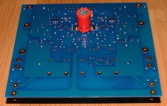
Today, 28th of June, I finally received the heat sink for the drivers (6 pcs of AAVID OS499, black anodized).😀
I also intend to mount two of the pre-drivers (Q9+Q10) on the same heat sink (on the back/solder side, the same as Mr Andrew intend to do/have done?)
I will post pictures when the heat sink has been mounted to the board so you could see how this could be done (6 drivers + two pre-drivers including Q13 on the same sink).
Regards 😎
😴
Today, 28th of June, I finally received the heat sink for the drivers (6 pcs of AAVID OS499, black anodized).😀
I also intend to mount two of the pre-drivers (Q9+Q10) on the same heat sink (on the back/solder side, the same as Mr Andrew intend to do/have done?)
I will post pictures when the heat sink has been mounted to the board so you could see how this could be done (6 drivers + two pre-drivers including Q13 on the same sink).
Regards 😎
Wires for the 100.2
Flodstroem
When my KSA100.2 was rebuild I obtained some rather expensive (18 gauge?) silver plated Van del Hull wire which appeared to be same thinkness as the originals. The originals were a soft multistrand cable compared to the less flexible VDH.
With hindsight I now realize that it was a (costly!) mistake as compared to a KSA50.2 the KSA100.2 now has less presence and spatial information in it's presentation than the KSA50.2.
So take care that you use thick multistrand wires when hooking up the output devices to the PCB.
Jozua
Jozua, thanks for the reminder. I shall use same type of wires that you suggest.
Thanks.
Regards 😎
Thanks.
Regards 😎
Boards missing
I was among the people ordering boards about Christmas time. But still, I have not received any boards. I guess they should have been here by now, I hope somebody can find out what has happened.
Regards
I was among the people ordering boards about Christmas time. But still, I have not received any boards. I guess they should have been here by now, I hope somebody can find out what has happened.
Regards
Harald, you had to ask Mark if he ever shipped the boards. It shouldn take more than 20 days of shipping (air mail) to you including Customs and Duties.
Check with Mark, its the only tip I can give you right now (n the Wiki I could see that you ordered 4 boards, and that you also have payed for them).
Regards 😎
Check with Mark, its the only tip I can give you right now (n the Wiki I could see that you ordered 4 boards, and that you also have payed for them).
Regards 😎
Is there any update on the shipping of the diodes?
Anyone have some photos to share of their progress?
Anyone have some photos to share of their progress?
crypt0wind said:Anyone have some photos to share of their progress?
I'm a slow builder.....
Attachments
Diodes
Mark
If you still have some diodes stock, please email me a quote. I need two more.
Dr. Strangelove
My pcb's are finished and waiting for their heatsinks to be anodized with the big heatsinks. Hopefully I should have them by early next week.
Floedstroem
It does indeed appear as if the amp is sensitive towards the type of hookup wire used. Adding an additional cheaper thicker multistrand Van den Hul CS122 with the existing Van den Hull CS18 to the output devices of my commercial 100.2 has definitely made the amp sound more natural with a 20% improvement in the soundstage. The only negative aspect is that seems to have slightly softened the bass firmness.
Interesting that such small changes can make or break the sonic character of an amplifier...
Jozua
Hi Jozua,
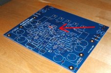
can you confirm what Thiele network is fitted?
Where is the NFB taken from? The standard PCB location?
can you confirm what Thiele network is fitted?
Where is the NFB taken from? The standard PCB location?
NFB standard PCB location as on the clone; with Thiele I assume you mean the snubber at the output, which is 5R6 and 100nF.
Hi,
Thiele network=series C+R in parallel to the load and parallel R//L in series with the load. Some or all of these components are often omitted without any deleterious effect, but equally can make the amplifier feedback circuit susceptible to reactive loads. Changes in the sound as the cable is swapped could fall into the reactive load problem.
I have not had a chance to experiment with the NFB location yet, but the Klone location which I believe copies the Krell location is plainly wrong in engineering terms, but this error may have no effect on the resulting sound.
I suspect you're hearing a combination of reactive load susceptibility exaggerated by incorrect NFB tapping point.
None of the commercial KSA's used the R/L series circuits, and all of them the RC snubber. All the ones I saw used 5R6 & 100nF.
The NFB (on my layout) was placed on the clone to make it easy for 100% drop-in compatibility with existing KSA's. Where would your preferred location be? The commercial KSA is also sub-optimal by the speaker load not being tapped symmetrically to the transistors; some pairs have over four times as long wiring to pass through.
Spectron Class-D amplifiers have a "remote sense" method with a double run of speaker cable, one being used for feedback at the speaker itself. Similar concept to voltage regulators with sense pins. The result with cheap Pro Audio cable is better than a single run of $800/m speaker cable - and I've heard it.
Hi Pwatts,
like I said, omission of some of the Thiele components may cause no deleterious effect on the sound. Krell may have deliberately used the Zobel alone to develop a "KRELL" sound. Does anyone know?
The NFB tapping point is not decided in my head. I would appreciate comment from both theoretical and practical viewpoints on moving the tapping to the output emitter resistors or even to the Zobel located on the speaker terminals. The problem I have is that both of these more technically correct locations have a LONG wire connection from tapping point to inverting input location. The introduction of that long wire with a 20k resistor in it may introduce much worse effects than simply accepting the standard location.
Experimentation may offer a solution.
What if the output Zobel were arranged as a cap to the ground terminal and a resistor to the live terminal and the junction between these two becomes the NFB tapping point (as Dr Cherry proposes)?
AndrewT
Interesting point you raise.
Just bear in mind the temporary hookup was done between the two transistor boards. I try to post a picture to show what I mean. Note that I am talking about the sonic impact of two wires the length of plus minus 6 centimeters each. One per channel.
The question now is what type of wire should one use if the amp is so sensitive? The originals were el-cheapo copper multistrand -virtually the same thickness as the more expensive CS18 which was now seems to be a step backwards.
The local Van den Hul agent now recomends using the same type of CS wire but a 12 gauge version.
Jozua
- Home
- Amplifiers
- Solid State
- Krell KSA 100mkII Clone