I agree. And that fact allows me to maintain that the Klippel system is a best estimate. As is the REW math functions. Not diminishing the value of either. Because anyone that has placed a mic in front of a loudspeaker knows a slight movement will give you a different measurement in the first place. I prefer to measure in an environment that is representative of reality versus the fabled reflection free zone. There are too many acoustic variables that are not compensated for when you are missing floor and ceiling reflections from your measurements.I would think more along the lines of a "shotgun" mike, which has a ver6y narrow field of coverage. It takes several elements to do this, but it is doable.
Also, all these "averaging" techniques - best case - reduce the reflections, they do not eliminate them. Elimination works best always.
It takes a fair amount of experience to know and understand this. ( I know that you have known this for a long time Earl. I read your papers when I was a young man 35 years ago!) I have measured in anechoic rooms, high up on ladders, ground plane and with this fancy math system. They all have utility. Guess which one I use most regularly? Although subwoofers, I have not proved out in my room. Working on PA horns and drivers right now.
Mark
Agreed, hence the creation of this thread, and hopefully some day a DIY Near Field Scanner will exist.Also, all these "averaging" techniques - best case - reduce the reflections, they do not eliminate them. Elimination works best always.
I will say, however, that getting reflections down to around -30dB gets nice results even though they are not anechoic.
This should be, I would think. the ultimate goal. The software is not too hard, but a reasonable cost automated data system would be.hopefully some day a DIY Near Field Scanner will exist.

Somewhere at the beginning of this @Dave Zan had a nice and simple idea for the hardware. At that time I didn't pursue developing the mechanical design because I had it in my head that the software would need to be first. At any rate, unless it's discovered that the microphone needs to be positioned to some crazy locations, it should be able to be developed semi-independently. And I agree, the hardware would be the high cost part of this.
So how automated are you thinking? Right now I am moving my mic stand a set amount along a drawn tape measure. A straight line and a consistent measurement. That gets us a on axis measurement. Take about 7 minutes for 25 measurements.
For horizontal polar measurements I am using a remote controlled turntable about $100 Canukistani dollars. The turntable is large enough that I keep the DUT at the centre of rotation so as to not influence the distance as it spins. Learned that one the hard way. Literally there is a hand held remote. Measure, hit the turntable button, measure, you know the drill.
Vertical polars. Now, that is a little more fun. I need to do this actually this week. My solution is a plywood semi-circlesetup with 15 degree positions fastened to a base so it is stable. I am missing a pipe to hold the mic. When I find the correct I.D. pipe I will cuts lengths and put the mic into each position manually. Getting the same distance will be using the end of the mic as a reference point. Not high tech. But doable by any reasonably handy person with a jig saw.
If I get ambitious I will make up a track with detents (shallow holes really) that can be used as a quick incremental measurement positioner for the on axis measurements. My mic stand has 3 feet, so a series of three holes at each increment will allow repeatable positioning without to much thinking.
Mark
P.S.
Anyone else have something that they have rigged up?
The advantage of the modal decomposition techniques that Klippel and I use, is that one need not be in the far field. Nearfield works nicely. This gives you a much larger free-space frequency range (window.) But then one still needs to do something at LFs to fit the modes when large reflections are present. There are also techniques for this.
No need to redevelop it! I'm still in the thread, just crazy busy at work, for the last 3 years.Somewhere at the beginning of this @Dave Zan had a nice and simple idea for the hardware...At any rate, unless it's discovered that the microphone needs to be positioned to some crazy locations, it should be able to be developed semi-independently.
I will try to post a picture of what I have so far, but probably not until next weekend.
But the basic idea is that the mic can be positioned conveniently in spherical co-ordinates, manually at first, stepper motors added easily as a second step.
I now have a precision measurement mic, a Bruel and Kjaer clone from MicW, and it calibrated pretty well.
Structure is nice thin wall, cold drawn aluminium tube from cross country race ski poles.
I need a mic interface probably a Topping E2x2.
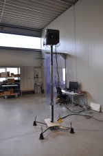
Seems that Kii is using a similar approach, see picture:I applaud your experiments! So far, you and Mark K. are the only other people on this forum to experiment with this method, and I do agree that your RMS average looks like a better fit... but the "sag" between 70Hz and 3.5kHz in the RMS Vs. Vector is interesting to me, there's clearly a lot of the room showing up below a few hundred Hertz. Daniel Krol's original paper also shows more variation at low frequency in small rooms too since room modes aren't quite the same animal as higher frequency reflections.
View attachment 1238119
Having good ground plane data would be nice to compare to also.
It codes from an factory visit article in hifi.nl:
https://hifi.nl/artikel/33047/Fabrieksbezoek-Kii-Audio.html
Is in Dutch, but basically they measure in a fabrication hall with 2mics and special software, it removes the need for costly anechoic rooms etc.
Attachments
People's perspective is very interesting.
I personally actually find the mechanical and hardware side of things the easy part.
Can also done on a very affordable level.
Aluminum extrusion beams are dirt cheap these days (at least in Europe) and can be even ordered to exact length.
The software and programming part for me is the more difficult side.
There is only one thing I like to point out again.
I said it in another topic as well.
Klippel is all nice for pretty graphs, but when designing loudspeakers we don't need all of it. (reviewing on a standard platform is something else)
A lot of cabinet specific issues, can be measured in different ways.
It's only the convenience, but mostly the issue with reflections that are interesting.
For the last part I have also thinking of testing a "anechoic tube" between speaker and the microphone.
Since we are only interested in the direct path between the mic and the speaker, we can basically make a "dampening enclosure" between the two.
In theory this should work.
Unfortunately currently I don't really have the space anymore to do much testing.
I think it's possible to combine a lot of great ideas here.
Keep in mind that Klippel is just one solution to a problem, not THE solution.
I also don't think it's necessary to have 100% anechoic measurements.
Getting down to about 80-100Hz would be great, the rest can be done with stitching, since the behavior down that low are very predictable.
Currently in my crappy small appartement, I can go as low as 170-200Hz or so.
Which isn't great for certain systems.
This is very much a nearfield measurement. What we are doing is not the same. But it is interesting to learn how they are measuring! Thank you!Seems that Kii is using a similar approach, see picture:
It codes from an factory visit article in hifi.nl:
https://hifi.nl/artikel/33047/Fabrieksbezoek-Kii-Audio.html
Is in Dutch, but basically they measure in a fabrication hall with 2mics and special software, it removes the need for costly anechoic rooms etc.
Mark
For your tube idea, how are you going to separate the tube resonance from your DUT? You may as well do only nearfield measurements. They are useful for understanding enclosure effects and not much else other than pretty graphs.People's perspective is very interesting.
I personally actually find the mechanical and hardware side of things the easy part.
Can also done on a very affordable level.
Aluminum extrusion beams are dirt cheap these days (at least in Europe) and can be even ordered to exact length.
The software and programming part for me is the more difficult side.
There is only one thing I like to point out again.
I said it in another topic as well.
Klippel is all nice for pretty graphs, but when designing loudspeakers we don't need all of it. (reviewing on a standard platform is something else)
A lot of cabinet specific issues, can be measured in different ways.
It's only the convenience, but mostly the issue with reflections that are interesting.
For the last part I have also thinking of testing a "anechoic tube" between speaker and the microphone.
Since we are only interested in the direct path between the mic and the speaker, we can basically make a "dampening enclosure" between the two.
In theory this should work.
Unfortunately currently I don't really have the space anymore to do much testing.
I think it's possible to combine a lot of great ideas here.
Keep in mind that Klippel is just one solution to a problem, not THE solution.
I also don't think it's necessary to have 100% anechoic measurements.
Getting down to about 80-100Hz would be great, the rest can be done with stitching, since the behavior down that low are very predictable.
Currently in my crappy small appartement, I can go as low as 170-200Hz or so.
Which isn't great for certain systems.
I missed typing another agreed to thought. Klippel is great at making equipment. I respect that. What I do not respect is the blanket marketing that basicly says that everything else is not Klippel. What I do not like is that these Nearfield scanner measurements are basically the same as what we can do with REW. In almost every way. But that is not getting the attention that the marketing machine at Klippel is getting. Solid measurements should be recognized as such. Klippel is a best guess method of testing using derivations that are used to smooth over the inherent spurious response to the item under test. It goes from nearfield to pseudo farfield and make computations that are presented as anechoic. These by themselves are pretty for marketing. But as mentioned do not reflect what will happen in a real room. For that you need the room approximation graph. The question for this is what room? The standard IEC test room? I have been to this room. I know of one set up not that far from me, and the original setup at the NRC in Ottawa. It is a modest sized living room. A shoe box shape. NOt reflective of modern rooms either here in North America, or the construction of homes in Europe where the walls are much more reflective all the way from the base on upwards. Here with standard stud walls our rooms are basically invisible below 30 hertz. Europe is by and large block wall construction. Very different.
So, taking a few of these things into consideration I submit that a real test, in a room that incorporates the rooms reflections at distance is a much more valueable measurement for actual design than anything that is anechoic.
Mark
Last edited:
Oh, that is not really what I mean.For your tube idea, how are you going to separate the tube resonance from your DUT? You may as well do only nearfield measurements. They are useful for understanding enclosure effects and not much else other than pretty graphs.
I meant more like a "tube" made from damping material.
Incl some additional layers of acoustic filters (perforated sheet board).
I will give some sketches when I have time 🙂
About Klippel.
Yeah I fully 100% agree!! 🙂
Btw, speaking of anechoic rooms, something I really DO NOT understand, is that companies which have such a room, don't use time window measurements in conjunction. It just doesn't make any sense at all.
Btw, speaking of anechoic rooms, something I really DO NOT understand, is that companies which have such a room, don't use time window measurements in conjunction. It just doesn't make any sense at all.
Well, if the anechoic chamber is large enough there is no need to gate the measurement. Even if it is not, you can calibrate your measurement curve using a know test device that you measure outside in an appropriate groundplane measurement and then find the difference or correction curve.
Having the opportunity to design a fairly large anechoic chamber taught me a lot. Especially when the chamber was not a cube. Many things needed to be worked out. And finding practical information as to what makes true differences was the greatest part of the work.
Like you, mechanical design and execution is not an issue. My issue is always the programming and the mathematics.
Mark
I have never seen a practical anechoic chamber that is 100% free of resonances.Well, if the anechoic chamber is large enough there is no need to gate the measurement. Even if it is not, you can calibrate your measurement curve using a know test device that you measure outside in an appropriate groundplane measurement and then find the difference or correction curve.
Very often you can see this back in the measurements.
The calibration method is one way, but in my experience, you're often able to use a pretty long time window.
Making it ideal to combine them with some simple near-field measurements.
Even maybe blend the actual direct anechoic measurements with them, just to get an overal impression.
For some reason, loudspeaker manufactures still seem to provide data and graphs with a lot of "noise" in them.
Making them sometimes practically unusable.
Makes you wonder if they even look at the data?
I still think these rooms are a bit old fashioned and overkill for loudspeaker design.
Mostly because loudspeakers are active source and relatively small.
Anechoic chambers are mainly used for devices where sound/noise is a byproduct.
In that case, controlling either the source or your measurements (either pre or post) is not possible.
(or very difficult).
It just happens to be working for loudspeakers for decades, mostly because data pro-processing was impossible.
But the last two-three decades that is not an issue anymore.
Guess we just still use them out of habit.
I only have access to an anechoic chamber when I am working in China. And we have not done a proper calibration curve there. In a small Town called Arnprior, in Ontario Canada there is a good chamber not too far from me. Convergent Technologies is the company. It is the same size as the large chamber at the National Research Council in Ottawa where I lived in the library in the late 80's. I have talked with them, interviewed as a contract consultant, but not much more.
Mark
Mark
So you lived in a library, now you're super smart! 🤓😀😉where I lived in the library in the late 80's.
(sorry, couldn't let this pass 😀 😀 )
Btw, some of those calibrations can be a bit of a weird chicken-egg story.
Probably not for the proper great big ones, but I have heard of a few stories where they kinda missed a turn in the process.
It's almost unbelievable, but it happens.
For most designs, I don't find them very useful for loudspeakers.
For all that time, effort (and money), you can get so close with just regular measurements.
Even more so when you just do them outside.
Which is often just a matter of planning
I have managed to fool them so far.So you lived in a library, now you're super smart! 🤓😀😉
(sorry, couldn't let this pass 😀 😀 )
Exactly. And the incorrect curve gets used for years.Btw, some of those calibrations can be a bit of a weird chicken-egg story.
Probably not for the proper great big ones, but I have heard of a few stories where they kinda missed a turn in the process.
It's almost unbelievable, but it happens.
I live in the countryside. Wind and Winter are my enemies. Right now Winter has raised his white head. About 140mm of snow over night. So little ground plane work now.For most designs, I don't find them very useful for loudspeakers.
For all that time, effort (and money), you can get so close with just regular measurements.
Even more so when you just do them outside.
Which is often just a matter of planning
I would be more worried about those low temps, at that point they actually can change things significantly.I live in the countryside. Wind and Winter are my enemies. Right now Winter has raised his white head. About 140mm of snow over night. So little ground plane work now.
Snow, is pretty good dampening layer though! 😀
But yeah, I used to work for a company where we mostly planned these things in late spring/early summer.
In that case we are talking also about big line-arrays.
Something that doesn't fit on any Klippel system and even not in a lot of anechoic chambers.
Additional benefit of having a nice BBQ afterwards as wel 🙂
If I had a property with plenty of land and space, I would just build something custom to be honest.
Doesn't have to be fancy, just something workable.
Interesting! Thank you for sharing that. I hope Google Translate is doing it justice, but this is, I think, the key part:Seems that Kii is using a similar approach, see picture:
It codes from an factory visit article in hifi.nl:
https://hifi.nl/artikel/33047/Fabrieksbezoek-Kii-Audio.html
Is in Dutch, but basically they measure in a fabrication hall with 2mics and special software, it removes the need for costly anechoic rooms etc.
It does seem like a similar concept, and it reminds me of this method too (which also works pretty well). I think it's worth a test to see if Kii's method is usable in a smaller space. My intuition says that it's less good in a smaller space because someone like Bruno would probably us it in one if it did, but I'm still curious.Bruno has developed a unique measuring method that eliminates the need to use an anechoic chamber. In the middle of the assembly hall, far enough away from all walls, there is a vertically extendable pole on which the loudspeaker is mounted, and the measurement is then done at a height of about four meters with two microphones: one close to the loudspeaker, and one at a somewhat greater distance
Software and programming is for me too, but in perspective, if someone does the software for free the hardware becomes comparatively expensive. 🙂People's perspective is very interesting.
I personally actually find the mechanical and hardware side of things the easy part.
Can also done on a very affordable level.
Aluminum extrusion beams are dirt cheap these days (at least in Europe) and can be even ordered to exact length.
The software and programming part for me is the more difficult side.
Have you considered documenting your experience and recommendations for those methods? I know some of it is more well known, but it could be beneficial to have the information centralized with some professional insight.Klippel is all nice for pretty graphs, but when designing loudspeakers we don't need all of it. (reviewing on a standard platform is something else)
A lot of cabinet specific issues, can be measured in different ways.
Agreed. There are many engineering solutions to a problem, and some can reveal what another might miss too.I think it's possible to combine a lot of great ideas here.
Keep in mind that Klippel is just one solution to a problem, not THE solution.
- Home
- Design & Build
- Software Tools
- Klippel Near Field Scanner on a Shoestring