Hi XRK, dont the mosfets need to attach to the main pcb? Whats the advantage of using two boards?
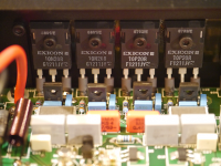
The main board has a way to mount the MOSFETs directly in the traditional underhung arrangement (very tedious way to mount OP’s). It also has next to the traditional solder pads, Molex MinifitJr locking connectors that we have used successfully in several other amps, that will allow remote flying lead mounting of the OP’s. The OP’s will mount to small helper “Snubber” PCBs that have on-board snubber resistor and caps and gate stoppers mounted directly next to the pins. The snubber boards also provide strain relief for the pins and serve as a clamp washer to distribute the bolt clamp force. But mainly, the remote mounting allows the OP’s to be mounted anywhere on the heatsink for optimal heat transfer and to de-couple the OP mounting process (drill and tap and screw-in) from the main PCB mounting, which can be on the chassis floor now. I have typically used flying leads about 8in long and they work fine with no oscillations in the Alpha series of amps.
The reason there is a smaller “mezzanine” PCB is so that the input stage and VAS can now be placed on a separate quickly removable PCB. This allows changes to the circuit and swapping of input stages quickly and cost effectively. In fact, with a push pull output stage like this, many different amplifier topologies can be used on this base main amp board which takes care of the PSU, the connection points, and the output DC offset speaker protection solid state relay and turn on delay.
In a way similar to the interchangeable amp core format used in the Yarra preamplifier, we now have a base amp to try many new Class AB or even Class A amp topologies that use push pull outputs.
This is especially useful in a new amp that is still undergoing development and debugging so that a new spin of the board only involves the much smaller and less expensive components.
Last edited:
You can consider to layout L & R channel front-end board as one common PCB (GND is also common). This may help to avoid using HBRs because there is no any ground loop between both channels.
Just place OPS of both channels to heatsinks. Connect it with bus wires.
Just place OPS of both channels to heatsinks. Connect it with bus wires.
Hi Walkalone,
The flexibility of having separate boards enables this amp to be made as a monblock, which may actuallu be the practical alternative given the weight of the large trafo and size of the heatsinks involved. Monoblocks tend to be quiter with regards to hum and other noise issues.
The flexibility of having separate boards enables this amp to be made as a monblock, which may actuallu be the practical alternative given the weight of the large trafo and size of the heatsinks involved. Monoblocks tend to be quiter with regards to hum and other noise issues.
Fantastic work JP!
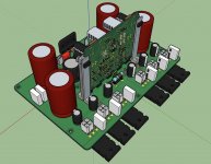
The mezzanine guide rail is a slick supportive piece 😉
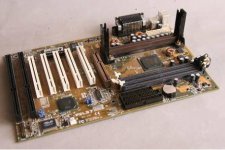
Well, reminds me of the Slot 1 mounting mechanism Intel had for the Pentium II processor. 🙂
Attachments
Last edited:
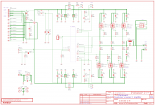
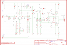
Hi XR, in the schematic, can you indicate which part is in the daughter and which part in the main board?
Thanks!
Thanks!
Things are in flux at this point as we are running some simulations of the PSU to spec' the trafo and CRC caps properly. Keantoken has models of the various Antek trafos, but intial sims are indicating that we will need qnty 2x 10,000uF 100v + 2x 10,000uF 100v caps per rail, and the trafo will need to be an Antek 500VA or 600VA 56v trafo. I still need to measure some Antek's I have on hand to see if they match the values given by the models.
These are subject to change as you can see the main board is rev00b and mezz board is rev00a.
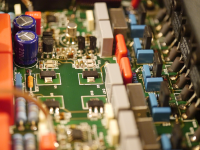
Basically, the mainboard contains the PSU, the outputs and ancilliary components like a DC protect SSR (still to be added). The real estate is getting tight with all these big caps so we will probably enlarge the main board.
Mainboard:

Mezzanine:

These are subject to change as you can see the main board is rev00b and mezz board is rev00a.
Basically, the mainboard contains the PSU, the outputs and ancilliary components like a DC protect SSR (still to be added). The real estate is getting tight with all these big caps so we will probably enlarge the main board.
Mainboard:
Mezzanine:
Attachments
Could the drivers mentioned by OStripper as replacements of drivers 3503 and 1381 be inserted? Thanks
If one can get new old stock of Toshiba 2SA1837 and 2SC4795, they certainly are some of the finest audio drivers ever made. Although I have tried the TTA004 and TTC004 and they seem to also do a great job.
If one can get new old stock of Toshiba 2SA1837 and 2SC4795, they certainly are some of the finest audio drivers ever made. Although I have tried the TTA004 and TTC004 and they seem to also do a great job.
Unisonic version of 2SC4793/2SA1837 available from Profusionplc. Anyway Toshiba TTC011/TTA006 has close relation with them.
Sajti
Last edited:
Hi Sajti, did you test those?Unisonic version of 2SC4793/2SA1837 available from Profusionplc. Anyway Toshiba TTC011/TTA006 has close relation with them.
Sajti
I have many but i don't know if I have to trust them 😕
Last edited:
Hi Sajti, did you test those?
I have many but i don't know if I have to trust them 😕
Not yet. However Profusion is trusty company.
Sajti
I'm using the TO-252 version of the 669 649 from unisonic with good results. Since moving to SMD parts, my measured DC offset has practically disappeared. One note about this TO-252 is that between the 669 and 649, the physical dimensions are slightly different for some reason, maybe by 1/4mm at most, but I use a template to install them and they fit differently. Width wise anyway. Love em so far
S
S
Not if we don't know what they are.
ZTX957/857 +/- 300V/85mhz/13pf Cob for SOT223.
For this new age , 10ma VAS's are GONE.
EF3's with 2ma pre-drivers , VAS's with <5ma ....
The ZTX's should give the same performance as the 1381/3503's.
The ZTX957 is 85MHz at 100mA whereas the 2SA1381 is 150MHz at just 10mA. 23pF Cob vs 3.1pF Cob. There is no comparison in that regard.
In this case we don't need high-current drivers like we would use in a BJT amp. The 3503/1381 would actually work fine in this amp, but I chose the Toshibas because they are more stable.
If speed isn't important then maybe they will work fine. But this is a bad substitution for a power amp as you may have to redo the compensation and you might just make it worse.
There is also the KSC2690A and KSA1220A.
- Home
- Amplifiers
- Solid State
- Keantoken's Aurum-X 300w Amp with LatFETs