For feedback, we can use a 1k resistor and 22pF or we can use a 10k resistor with 2.2pF. I have gotten complaints in the past about using small capacitors, but I don't think there is an issue with 2.2pF in this position with any sanely routed PCB.
The reason I want to use a 10k resistor is that a 1k resistor dissipating 5W might cause issues with DC offset due to thermal problems. Unless we swear off DC coupling for this amp entirely (or design a servo), that is something we want to avoid.
The reason I want to use a 10k resistor is that a 1k resistor dissipating 5W might cause issues with DC offset due to thermal problems. Unless we swear off DC coupling for this amp entirely (or design a servo), that is something we want to avoid.
We can ask JP to put a special turret mounting stud that allows 2 resistors to be mounted on top of each other and gives good air flow. Two of these in parallel or 4x4k should give good thermal dissipation. Good metal thin film, carbon thin film, or even better, bulk metal non inductive resistors work really well here.
Even running only 8R load I would design the amp for delivering 4-5R load to be on the safe side. Have you done a SOA simulation like here for different reactive loads? ... linear degradation of SOA if heatsink/die temperature increases......
A single pair of SJ49/SK135's can give 100W into 8ohms, which is 5A peak.
...
BR, Toni
The amp is designed to survive 5.5ohms with the worst phase angle with the minimum heatsink, to be compatible with 8ohms but not indestructible into 4ohms. 4ohms requires a very good headsink or dual-die FETs.
Hi Garrath,
only one comment. I would change the gate resistors for the N and P channel latMOSFETs so that their time constants correlate.
only one comment. I would change the gate resistors for the N and P channel latMOSFETs so that their time constants correlate.
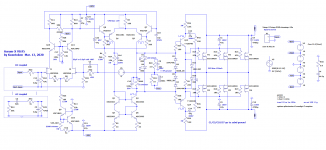
If you invert D2, D3, D4 and D5 you'll get current limiting which will protect the output stage (to some extent) in the event of a short.
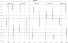
Also, try putting a capacitor across R3 an re-running your square-wave response. I think you'll be pleased with the result.
Also, try putting a capacitor across R3 an re-running your square-wave response. I think you'll be pleased with the result.
I tried those things already. The protection works fine although no one gives it a chance because it looks wrong.
Hi Nico, nice to see you again. I'm not Gareth, though I know him.
As far as SOA concerns, what is the worst case DCR of an 8 ohm speaker? I decided it was 5.5ohms. I guess someone will tell me it's 4.5 ohms. What is the worst case DCR of a 4 ohm speaker?
Hi Nico, nice to see you again. I'm not Gareth, though I know him.
As far as SOA concerns, what is the worst case DCR of an 8 ohm speaker? I decided it was 5.5ohms. I guess someone will tell me it's 4.5 ohms. What is the worst case DCR of a 4 ohm speaker?
As far as SOA concerns, what is the worst case DCR of an 8 ohm speaker? I decided it was 5.5ohms. I guess someone will tell me it's 4.5 ohms. What is the worst case DCR of a 4 ohm speaker?
That's what I meant by "in case of a short". With current-limiting diodes, you should be able to survive a worst case of 0. (LTSpice won't take that, though, so I usually just use something really small, like 0.004 ohms.)
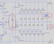
This output stage (for instance) should survive a brief short (although the heatsink is going to heat up pretty quick):
Attachments
Granted, but for speaker loads what we want is continuous ratings, at least that is what I assume we want on DIYAudio. The diodes will limit peaks but won't help with continuous ratings much I don't think.
70W into a short at 46V rails means 1.52A. Does 4.7Vgs across 6x 2SK1058 really limit to 1.52A?
Edit: It looks like you mean 70W per MOSFET which means 420W.
BTW, the diodes work as I drew them and I still maintain this until someone shows me them not working. But maybe I could reduce the voltage to limit current peaks more.
Last edited:
Yes, that's right, it's per device. They won't stand 70W long, but with the 2SJ162s pulling another 420W they should last long enough for the fuse to blow. (That's the theory anyway.)
...
As far as SOA concerns, what is the worst case DCR of an 8 ohm speaker? I decided it was 5.5ohms. I guess someone will tell me it's 4.5 ohms. What is the worst case DCR of a 4 ohm speaker?
Yes, 8R Speakers are around those 5.5R. IMHO many 4R speakers are in the range of 3.1R - 3.3R. This is why I designed my 4-8R amps to be stable for continuous load at 2R - 2.5R.
Of course there is the crest factor, but this is another discussion.
BR, Toni
Well, here are my thoughts.
The amp has 450mA bias current. At +-80V rails at idle, that is 72W idle dissipation. If I go up to dual-die Exicons, that will be 144W. This begins to seriously eat into our heatsinking ability. Furthermore the dual-die versions don't have the Vgs matched option so we would be using source resistors again.
So what I propose is this:
4 pairs of 10x20-S Exicons, 300W output with DIYAudio 0.31C/W or better heatsink.
70V for 8ohm
60V for 6ohm
50V for 4ohm
That way those who want the best compatibility can build the 4ohm version, and those who want the best headroom can build a version suited for their speakers.
FWIW, derating our amps this way has some strong assumptions. It assumes that someone, somewhere, will find the worst 8ohm speaker, then play a sine wave at full volume at the frequency with the worst phase angle for an extended period. Or that someone might do the same thing into a fake speaker load. Neither of these scenarios are very relevant to Hi-Fi listening. So I don't consider it a big deal to fall a bit short of the required power for this scenario, although it does give a good buffer.
On the other hand we could instead escalate the worst case power requirement until everyone is satisfied. We can collect everyone's worst case scenarios and put them together and eventually the FBI will arrive to ask us why we are attempting to purchase a nuclear power plant.
BTW, has anyone noticed that the TO-3 version of the 20N20 only has 60W of SOA at 60V? The SOA line looks like secondary breakdown. If this is not a mistake then it is pretty weird.
http://www.exicon.info/PDFs/ecf20n20.pdf
http://www.exicon.info/PDFs/ecw20n20.pdf
My strong advice is to find a compromise and go for just one version, also for the sake of versatility.
With different output stage rails, how about input/driver stage rails?
For example a 50V 4 0hm versions would have 60V input rails which ask for different resistor values and so on?
With different output stage rails, how about input/driver stage rails?
For example a 50V 4 0hm versions would have 60V input rails which ask for different resistor values and so on?
Last edited:
I guess that is why the Hafler DH-500 uses a fan.The amp has 450mA bias current. At +-80V rails at idle, that is 72W idle dissipation. If I go up to dual-die Exicons, that will be 144W. This begins to seriously eat into our heatsinking ability. Furthermore the dual-die versions don't have the Vgs matched option so we would be using source resistors again.
Profusion sells ECF20P20-S & ECF20N20-S, refer to
Lateral MOSFETs (Buy Online) | Profusion
You do not necessarily increase the total bias if you want the first watts be class A. Even with low bias per device the laterals perform very good: have a look here...
The amp has 450mA bias current. At +-80V rails at idle, that is 72W idle dissipation. If I go up to dual-die Exicons, that will be 144W. This begins to seriously eat into our heatsinking ability. Furthermore the dual-die versions don't have the Vgs matched option so we would be using source resistors again.
...
Think it's a simple graphic mistake with a wrong log scale: the current range is 0.1A to 100A for the TO3 devices whereas the current range is 0.01A to 100A for the TO264 devices. If the values would be true you can throw your ECF double die types into the bin ......
BTW, has anyone noticed that the TO-3 version of the 20N20 only has 60W of SOA at 60V? The SOA line looks like secondary breakdown. If this is not a mistake then it is pretty weird.
http://www.exicon.info/PDFs/ecf20n20.pdf
http://www.exicon.info/PDFs/ecw20n20.pdf
BR, Toni
... Furthermore the dual-die versions don't have the Vgs matched option so we would be using source resistors again....http://www.exicon.info/PDFs/ecw20n20.pdf
Using ECF20x20-S or ECW20x20-S you get matched pairs - this is from https://www.profusionplc.com:
The S version has been tested and graded into colour bands based on the technical spec shown below to ensure close matching. We cannot guarantee a specific colour band upon request but orders will be supplied from the same colour band. If you have a particular requirement, please contact us before ordering.
BR, Toni
XRK was concerned about the 5th harmonic so I bumped it up to 150mA per device. I could use more devices at 125mA, but the 5th harmonic would just be moved up to a higher power level. A slightly higher bias is the way to fix this. A lower bias will worsen it.
My mistake on the dual die -S grades.
Okay, next proposal. We stick with 70V rails.
8x ECX10x20-S for 6-8ohm 300W with DIYAudio 0.18C/W heatsink
8x ECW20x20-S for 4ohm 600W with DIYAudio 0.18C/W heatsink
This way the only differences between versions will be the output transistors, PSU and maybe compensation changes.
- Home
- Amplifiers
- Solid State
- Keantoken's Aurum-X 300w Amp with LatFETs