500W Inverter:
Have you tested other combination to see what other V beside the list as 160 220 and 380. Wonder if can get 280 or 300 on this module.
Have you tested other combination to see what other V beside the list as 160 220 and 380. Wonder if can get 280 or 300 on this module.
160 into a Delon will give you 320, you can wire the 18V output in series with the 160 to either boost or buck.
Have anyone ever thought of PS from satellite box? It should have enough to power to run this project. I have seen people give them away on Craigslist everyday 😀 I haven't checked others old home audio equipment yet but I believe they all standard design with 12v, 5v, and 3.3v.
Seem like all wires that has the same voltage connect to the same terminals so you only need to hook up 1 wire for the voltage need and whatever the current of the device need, it will draw enough to run until it runs out the current.
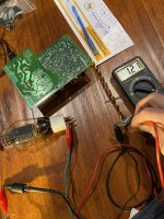
Here is my test on old satellite box PS, 12v and 5v are perfect for the tubes filament where it can run without fan. It would be great to use the satellite case as well since all the RCA and PS jack holes in the back are setup. 🙂
Seem like all wires that has the same voltage connect to the same terminals so you only need to hook up 1 wire for the voltage need and whatever the current of the device need, it will draw enough to run until it runs out the current.
Here is my test on old satellite box PS, 12v and 5v are perfect for the tubes filament where it can run without fan. It would be great to use the satellite case as well since all the RCA and PS jack holes in the back are setup. 🙂
Attachments

Wow thank you for all of this info Kodabmx!
Just to be crystal clear, should the 12v ground be connected to the ht ground and the chassis? I currently have only the ht and 12v grounds isolated and im getting significant hum.
Just to be crystal clear, should the 12v ground be connected to the ht ground and the chassis? I currently have only the ht and 12v grounds isolated and im getting significant hum.
Hello, one more question for ya:
How do you keep the hum from the 150W inverter from coupling to the amplifier stage? I'm heavily filtering every section of the power supply and using ample grid stoppers as RC filters, but the faint high pitch hum of the inverte remains. Is physically isolating them in seperate chasis necesary?
How do you keep the hum from the 150W inverter from coupling to the amplifier stage? I'm heavily filtering every section of the power supply and using ample grid stoppers as RC filters, but the faint high pitch hum of the inverte remains. Is physically isolating them in seperate chasis necesary?
I've not encountered that issue with the 150W supply. Perhaps a small common mode choke on the output would help? They are supposed to switch at 37kHz (if you got the one I think you're talking about) so you shouldn't hear it even if it was leaking through. There is an AC output version that switches at 20kHz.
If you look up how to use the SG3525 chip, you can modify the frequency if you need to.
If you look up how to use the SG3525 chip, you can modify the frequency if you need to.
I figured out that if you install a snubber in the empty spot in front of the mosfet switchers the ringing will be minimized.
Thanks for the great idea, it works perfect now!
Thanks for the great idea, it works perfect now!
Sure!
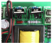
In picture 1, placing an RC snubber in resistor and capacitor silkscreen slots will help aid in preventing oscillation. The exact values will depend on the load, I ended up using 22nf and 2.2k.
The second picture shows the greeny capacitor you can alter to change the oscillation frequency. I ended up bumping mine up to around 100k using the formula on the datasheet.
Attachments


AH. You're using a different version. Mine seems to include the RC snubber from the factory. The 1uF cap on pin 8 of the SG3525 can be made 22uF for a ~1 second PWM ramp up, too.
Attachments
Last edited:
Looking for LLC DC 220v and DC 6.3v version
There is 60w smps version with DC 250v output, unfortunately it’s not adjustable output to my need DC 220v
I ask the seller and confirm.
Anyone ever adjust/mod these smps ?
There is 60w smps version with DC 250v output, unfortunately it’s not adjustable output to my need DC 220v
I ask the seller and confirm.
Anyone ever adjust/mod these smps ?
I have no idea how to modify an LLC SMPS. Mine determine output voltage by step up ratio of the coil.
How much power are you talking about? Why not use a 30V 5W zener in series with the output? Or a string of them as shunt regulation?
How much power are you talking about? Why not use a 30V 5W zener in series with the output? Or a string of them as shunt regulation?
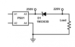
The part is rated for 5W, the load (80mA) implies 2.4W Pd in the zener. Max current would be 166mA but nobody tries to wring 5W out of a 5W device 😀 If you need more power handling, use lower voltage zeners in series. 1N5352B is 15V for example.
Last edited:
- Home
- Amplifiers
- Power Supplies
- Kanged switching power supply for a tube amp