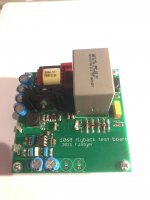
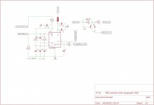
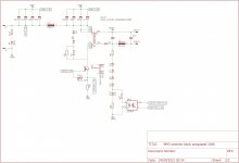
I built this psu B+ with seperate ground dc diodes 6.3v, but I have huge humming noise.
I hope anyone can help.
More C ? Where ?
I simulate this with good almost no ripple.
Is the noise from the filament ?
Those caps value are odd, that’s what I got after measurement.
Thank you
I hope anyone can help.
More C ? Where ?
I simulate this with good almost no ripple.
Is the noise from the filament ?
Those caps value are odd, that’s what I got after measurement.
Thank you

I am glad I keep this link as favorite 😀 I don't time to start this yet but got all the parts need. kodabmx, any chance you do a summary on fist page of your first post? Such as does it work with rectifier tube or just diodes only, and what kind of diodes that compatible, chokes, ground problem, etc...
Now come to the rc snubber, saw the pic but not sure how to apply if it happens to mine. May be calico88 can explain more detail how to so others can follow. 🙂
Now come to the rc snubber, saw the pic but not sure how to apply if it happens to mine. May be calico88 can explain more detail how to so others can follow. 🙂
This thread needs more switchers. Switchers are easy peasy (Flybacks) once you get it, but that applies to everything in life i guess.
I just recently finished a prototype for a 6-12V or 12-24V to -60V 100mA flyback. For bias purposes. Ripple in the audio range is non-existent. and there is only some Megahurtz ripple that i keep out with some 1206SMD beads. Works really well actually.
And a 10-14V in Flyback to 450V 100mA for well guess the purpose. Im gonna use two cores to go from 24VDC to 450VDC 200mA next..
Next up is a Buck from 24VDC to 6.3 8A guess the purpose..
Attachments

Do you mind posting the schematic for the 10-14v to 450v flyback converter?
Or if not, a verbal description of the design blocks?
Having a lot of problems with my own prototypes, feels like I'm missing something.
Also, where does one source reliable flyback transformers for this purpose?
Thank you.
Or if not, a verbal description of the design blocks?
Having a lot of problems with my own prototypes, feels like I'm missing something.
Also, where does one source reliable flyback transformers for this purpose?
Thank you.
I was going to build a 12V to 280V boost based on SG3525 like I've been buying but the transformer costs more for me to buy than the entire boost module so I just buy them ready-made.
TI-EF25-1068 FERYSTER - Transformer: impulse | power supply; 45W; Works with: UC3843 | TME - Electronic components
Data from Ferryster.
Lprim 10.89 µH ±10%
Ratio 1:10
Ipeak 15.8 A
Isat >18 A
fosc 70 kHz (UC3843, DCM)
Rsc 0.075 Ω (Ipeak = 13.33 A), 0.068 Ω (14.7 A) 5 W
I use IRFP240/UC3843 for my proto nice slow fet, no need to go to LT1243 for the better fall times, just use a 6K/W cooler for the fet. Less garbage in means less garbage out on the secondary. Not that you cannot get somewhat higher efficiency, but most of your dissipation comes from the 1V current sense resistor. I used a TO220 resistor for that, but theres no reason you cannot get away with three 0.22R 2W metal oxides in parallel to get to 82 or 68mOhm
Next thing on my list is to take two of these cores, and put the primaries in series, and the secondary in parallel.
CNY64 has horrible current transfer ratio, a 4N25 will work better. But i wanted to be able to stack this supply on top of something else, into the KV range.
This is the Fet i plan on using for the improved version. There is no need to have both a slow fall time FET and a slow fall time output on the UC3843
AOT296L ALPHA & OMEGA SEMICONDUCTOR - Transistor: N-MOSFET | unipolar; 100V; 50A; 54W; TO220 | TME - Electronic components
If you want better regulation than whit a zener stack, TL431 is the way to go.
Attachments
Last edited:
Thank you for your post, very informative.
Would one still need to use some zeners before the TL431 to avoid exceeding the collector voltage?
Would one still need to use some zeners before the TL431 to avoid exceeding the collector voltage?
What do you folks use for step up transformers?
A while back I looked at switching psus for step up 320 but found getting transformers to be difficult. Lots of step down but very few step up.
A while back I looked at switching psus for step up 320 but found getting transformers to be difficult. Lots of step down but very few step up.
I've been using prebuilt modules.
I'd try this if I was going to design instead though: 12V To 255V 300V EC42/EC4045 Horizontal High Frequency Transformer Inverter Booster|AC/DC Adapters| - AliExpress
I'd try this if I was going to design instead though: 12V To 255V 300V EC42/EC4045 Horizontal High Frequency Transformer Inverter Booster|AC/DC Adapters| - AliExpress
Hey kodabmx, when you use this setup, what do you do when you need an elevated heater voltage for a cathode follower or cascode?
I use a tube that doesn't need the elevation TBH. I've never elevated a heater.
If I needed to, I'd run another small 12V SMPS and elevate it's output for heaters.
If I needed to, I'd run another small 12V SMPS and elevate it's output for heaters.
I've recently built a small EL84 SE amp using this module and my experience has been quite good. Voltage is stable at about 80mA current draw. i had some "flapping" noise (not very loud even on high efficiency speakers) but found that re-arranging the heater wiring to keep it away from signal wire resolved this, now it's dead quiet.
I've got a unique problem here with this Crown. From 1956!! It's a rare stereo amplifier, used for a studio monitors back then... but instead of making dual mono blocks, they combined the power output of the 2 power Transformers to get the 490 VDC... needed to power 4x EL37s the AC outputs at the individual Transformers are about 365AC... So i'm just looking to bump it up.A hundred and twenty five volts. And ideally, it would be nice to get APC b that I could have ready-made. That would give me the standard pre. Amp tube voltage of about 215 to 250... And DC heater voltage, since it's a nice hi fi Amp. 30W per side rms. I regretfully, i'm a little bit behind on some of this stuff, because this rather new... but if it can be done, which i'm sure it can, i would just like to know a little bit in advance from somebody who has a little bit more of a line on this.It uses an ATX power supply (or a 12V battery/car) to heat the heaters and drive boost converters for HV, including one that boosts 12V to 13.5V to get 440V from a 380V supply.
I use an EVGA 750W G2 supply: EVGA - Products - EVGA SuperNOVA 750 G2, 80+ GOLD 750W, Fully Modular, EVGA ECO Mode, 10 Year Warranty, Includes FREE Power On Self Tester Power Supply 220-G2-0750-XR - 220-G2-0750-XR
into the following:
This module gives the boost from the LV supply: 1200W 20A DC Converter Boost Car Step-up Power Supply Module 8-60V to 12-83V | eBay
This module gives me 280V for the preamp/buffer/headphone amp: DC-AC Converter 12V to 110V 200V 220V 280V 150W Inverter Boost Board Transformer | eBay
This module gives me the 440V for the power stage after boosting the input to 13.5V: MINI DC-AC Inverter 12V to 18V220V/380V 500W Boost Step UP Power Module New Hot | eBay
This works far better, and for less money than a conventional linear supply.
It powers an integrated amp with 20 tubes.
I meant to leave the schematic here. Sorry to hijack your post, but I mean, if you help me out, I'll help you out. I'm sure that means money. Lol.Here is a photo of the amp it powers. Yes, there's a nixie to show which input, and regulated screen supply per channel.
Attachments
don't waste your money and time to power anode tube amplifier with this 500w converter it seem Koda have change his mind about it he drives his power tube amplifier now with linear one with good pi filter refer to personnal message I receive today from him
for filament power supply you can go to smps as it's work very good for me since 6 years without any bad issue
for filament power supply you can go to smps as it's work very good for me since 6 years without any bad issue
- Home
- Amplifiers
- Power Supplies
- Kanged switching power supply for a tube amp