Hello all
Have started to make a new k8010/11 test rig but has started to turn into an open useable chassis for mods and upgrades and trying to make it useable with a common-sense approach that will make it safe as possible to use .... as an open frame experimental platform that can be used
Have started to make a new k8010/11 test rig but has started to turn into an open useable chassis for mods and upgrades and trying to make it useable with a common-sense approach that will make it safe as possible to use .... as an open frame experimental platform that can be used
Hello DIY audio members .. a few pics of my new test bench. I wanted a platform to experiment with different power transformers and output transformers from other manufactures to make sure every thing worked OK .. Plus to try different valves and component values etc ... on a safe as can be achieved test bench for me, well that is the plan so happy to share is this helps other constructors.
Will post the pictures in constructional order.
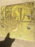
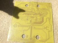
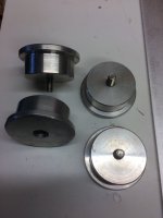
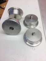
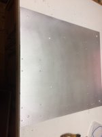
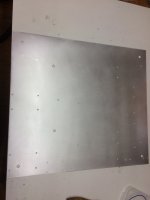
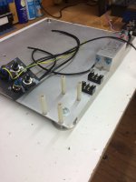
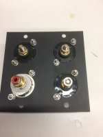
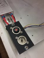
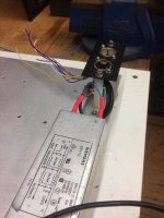
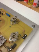
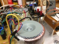
so we have the new chassis plate with lath turned feet and the mains filter added (had it kicking around so thought might as well use it. So a experimental base for mods and improvements etc.
Will post the pictures in constructional order.
so we have the new chassis plate with lath turned feet and the mains filter added (had it kicking around so thought might as well use it. So a experimental base for mods and improvements etc.
Attachments
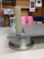
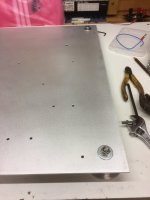
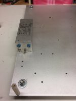

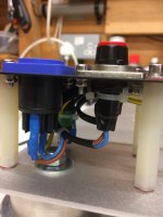
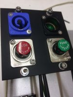
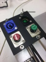
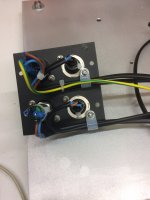
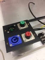
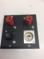
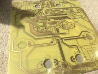
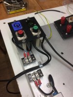
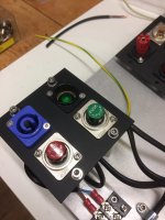
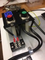
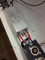
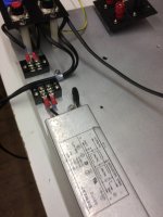
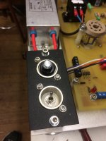
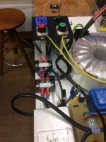
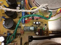
more pics ... power supply connections and mains filter and protected terminals etc .. plus main power on/off switch
Attachments
-
 IMG_0068.JPG224.6 KB · Views: 55
 -
 IMG_0069.JPG300.5 KB · Views: 53
 -
 IMG_0070.JPG374.1 KB · Views: 63
 -
 IMG_0118.JPG384.9 KB · Views: 63
 -
 IMG_0067.JPG326.7 KB · Views: 61
 -
 IMG_0066.JPG323.5 KB · Views: 59
 -
 IMG_0065.JPG349.3 KB · Views: 64
 -
 IMG_0064.JPG366.5 KB · Views: 55
 -
 IMG_0063.JPG307.8 KB · Views: 64
 -
 IMG_0062.JPG340.9 KB · Views: 64
few more final pics
Attachments
-
 IMG_0067.JPG326.7 KB · Views: 67
 -
 IMG_0068.JPG224.6 KB · Views: 61
 -
 IMG_0069.JPG300.5 KB · Views: 54
 -
 IMG_0070.JPG374.1 KB · Views: 57
 -
 IMG_0118.JPG384.9 KB · Views: 64
 -
 IMG_0119.JPG374.6 KB · Views: 61
 -
 IMG_0120.JPG330.2 KB · Views: 62
 -
 IMG_0121.JPG389.3 KB · Views: 65
 -
 IMG_0122.JPG421.1 KB · Views: 64
 -
 IMG_0123.JPG300.5 KB · Views: 62
 -
 IMG_0124.JPG293.8 KB · Views: 63
 -
 IMG_0125.JPG318.6 KB · Views: 63
 -
 IMG_0126.JPG358.8 KB · Views: 61
 -
 IMG_0127.JPG403.8 KB · Views: 59
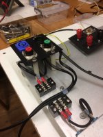
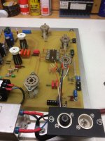
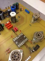
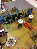
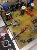
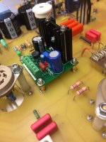
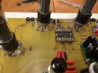
100 ohm Anode resistors still to be added on the tag board .. reason for this for easy replacement
few more .. will update more later when fully complete
Attachments


Hello
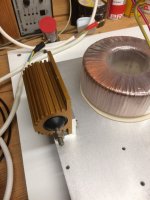
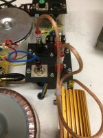
Added the dummy load the other day on the test chassis plate .. I had this power resistor kicking around for years so thought I might as well use it .. obviously you don't need this high wattage but I had it at hand (8 ohm)
Also output transformer placed in position before final fixing
Added the dummy load the other day on the test chassis plate .. I had this power resistor kicking around for years so thought I might as well use it .. obviously you don't need this high wattage but I had it at hand (8 ohm)
Also output transformer placed in position before final fixing
Attachments
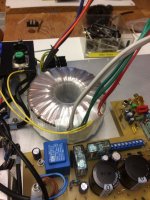
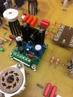
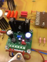
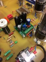
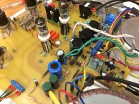
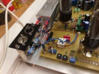
I have completed a small modification by adding a separate voltage regulator PCB.
This is 12 DC used for the control side of the power amplifier as before was a 12 DC un regulated supply that used to run higher then I liked. The trouble I find is that most UK transformers are rated 230v ac primary .. my house can range from 238v to 242 volts (we have over head power lines)
My main valve power transformers now have 3 primary taps to help with this (230 / 240 / 245) I suppose I could have used a switch mode power supply but I like the linear reg approach .. anyway has been tested and works very well so pleased with this modification
Attachments


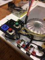
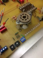
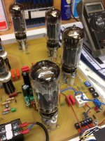
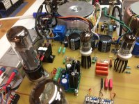
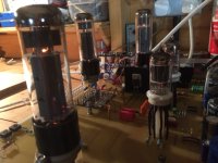
Tried the heaters only today .. all works OK
don't worry the wires are not near the hot valves but as said this is a test bench chassis for mods and my newly manufactured power and output transformers but still waiting for those to be delivered .. I do have 2 Sowter output transformers that will be tested when up and running .. but my music room is out of action at the moment as being used as a dumping ground as decorating at the moment 🙄
don't worry the wires are not near the hot valves but as said this is a test bench chassis for mods and my newly manufactured power and output transformers but still waiting for those to be delivered .. I do have 2 Sowter output transformers that will be tested when up and running .. but my music room is out of action at the moment as being used as a dumping ground as decorating at the moment 🙄
Attachments
another batch of output transformers I have ordered to experiment with is attached
the mains power transformers are now made in the UK used to use (Terry) from Canterbury windings but he kindly recommended another manufacture before he retired based in the UK
regards
the mains power transformers are now made in the UK used to use (Terry) from Canterbury windings but he kindly recommended another manufacture before he retired based in the UK
regards
Attachments
Hello All
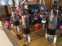
Well finally got the test chassis completed, I wanted this to test various makes of valves and power and output transformers and experiments before I committed to a very expensive case enclosure etc.
some pics before final power up
Well finally got the test chassis completed, I wanted this to test various makes of valves and power and output transformers and experiments before I committed to a very expensive case enclosure etc.
some pics before final power up
Attachments
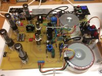


I did have a little bit of an issue with the biasing, but would you believe this was a issue with as old NOS LM3914 LED driver chip now replaced all ok and all valves bias ok .. But next will be the final sound check
to be updated later in the coming months
to be updated later in the coming months
Attachments
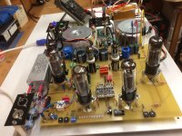

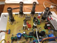
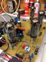
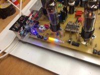
Final Bias
well for to night all looks good for a final sound audition ? I always get nervous when I power these up for the 1st time
well for to night all looks good for a final sound audition ? I always get nervous when I power these up for the 1st time
Attachments


Hello All
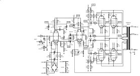
so this version was the k8011 model using EL34 tubes .. 90 watts per channel and the 1st 15w in class A, so now need to find a suitable case for 2 Monoblock's
My next build will be the k8010 version using KT88 valves this is 60 watt pure class A
Also note I am not using the velleman transformers but have sourced a UK manufacture for a better replacement but yet to be tested
diagram of the KT88 version
Attachments
- Home
- Amplifiers
- Tubes / Valves
- K8011/K8010 PCB build thread