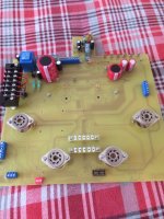
Picture of the power supply, but note this needs to be updated with a couple of mods
1. regulated 12 volt power supply for the control relay side of the circuit
2. Choke added in the HT power supply

1. regulated 12 volt power supply for the control relay side of the circuit
2. Choke added in the HT power supply
Ok .. my new build but is work in progress (only one channel shown)
this will be going into a case once I have found one suitable
Mains transformers by Terry from Canterbury Transformers .. and output transformers from UK supplier transSonic
watch this space ..
this will be going into a case once I have found one suitable
Mains transformers by Terry from Canterbury Transformers .. and output transformers from UK supplier transSonic
watch this space ..
Attachments
2 velleman pcb's on ebay
very rare .. be quick before I change my mind 😉
https://www.ebay.co.uk/itm/256219824794
very rare .. be quick before I change my mind 😉
https://www.ebay.co.uk/itm/256219824794
Hello
I have removed the PCB's from eBay (mainly due to lack of interest)
But I do have the PCB's available if and when people need them .. just letting you all know 👍
regards
I have removed the PCB's from eBay (mainly due to lack of interest)
But I do have the PCB's available if and when people need them .. just letting you all know 👍
regards
Also please note
I have found a UK supplier to make the power supply transformers and output transformers
all other components are fairly easy to obtain (but I can help if needed)
all the best
I have found a UK supplier to make the power supply transformers and output transformers
all other components are fairly easy to obtain (but I can help if needed)
all the best
hello so a few upgrades that I have added
a voltage regulator PCB for the control section of the power amplifier to keep every thing at 12V DC

a voltage regulator PCB for the control section of the power amplifier to keep every thing at 12V DC
Also have added a relay driver transistor in a socket to aid maintaintence (plus easy experimental changes in devices)

Hello
So for a while now I have been trying to make a k8011 k8010 version with the valves showing on top plus to give easy maintenance ... also, trying to fit into an existing hifi2000 (modushop) case .. as there is only so much metal fabrication one can complete in the shed.
I normally make versions of this design in a fully enclosed rack case as there are lots of versions out there to purchase from the normal suppliers.
Hopefully the pics make sense of what I am trying to achieve
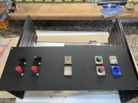
so rear panel completed, this is a generic design that I can use for other designs so keeps costs down
So for a while now I have been trying to make a k8011 k8010 version with the valves showing on top plus to give easy maintenance ... also, trying to fit into an existing hifi2000 (modushop) case .. as there is only so much metal fabrication one can complete in the shed.
I normally make versions of this design in a fully enclosed rack case as there are lots of versions out there to purchase from the normal suppliers.
Hopefully the pics make sense of what I am trying to achieve
so rear panel completed, this is a generic design that I can use for other designs so keeps costs down
Attachments
The main internal work looks like this .. houses the power transformer and output transformer and terminals for front and rear connections.
Both the front panel and rear panel can be removed and the complete amplifier chassis slides out and removed for repairs and mods etc. this is why I made a test bench rig examples in the historic posts.

Both the front panel and rear panel can be removed and the complete amplifier chassis slides out and removed for repairs and mods etc. this is why I made a test bench rig examples in the historic posts.
couple more just for info ...
The pic below is for the rear panel ...


the above pic is for the front amplifier panel
The pic below is for the rear panel ...
the above pic is for the front amplifier panel

- Home
- Amplifiers
- Tubes / Valves
- K8011/K8010 PCB build thread