Latest fun..😀
The gain has been increased.
However this is very noticeable in the U/L mid position selection when the RH FB is removed. Interesting to try. Still works with all tubes.
It might be interesting if the mid position was triode..Umm just thought haven't tried it, that's got to be on the cards..😀
Regards
M. Gregg
Attachments
Last edited:
While playing about,
I also tried some old Audio Note copper/paper in oil caps (in the box of bits) to compare against the Audyn copper. 🙄 well you have to play..😀
I have never been a fan of the audio note caps..however you have to give it a go!
Triode connected OP tubes next because the gain is probably going to give more drive. Perhaps another switch..
Regards
M. Gregg
Attachments
Last edited:
Semi's are like a resistor plus cap.
You've got it backwards 😉
Mind that lowering the cathode impedance effects the tubes' output impedance as well.
That's probably the effect we are hearing if it's big enough.
You've got it backwards 😉
Mind that lowering the cathode impedance effects the tubes' output impedance as well.
That's probably the effect we are hearing if it's big enough.
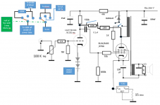
Latest play..very simple modification,
Triode in mid position no RH FB.
This works well with the increase in gain (390K).
I think its better than the U/L connection.😀
Its early days however I think the mod will be staying.
So now I have:
Switch position 1 is 200K RH FB for Ecc83 etc, RH Zener.
Switch position 2 is NO RH FB and triode connection.
Switch position 3 is 100K RH FB for Ecc81 etc, RH Zener.
So as it stands now😛ic
Regards
M. Gregg
Attachments
I think the 47k is superfluous, anode should be 100k, and you should use an un-bypassed resistor instead of the diodes. I guess that would work much better?
I guess it would..😀 (I'm not trying to trash the RH amps they are great. But this isn't an RH amp is it!)
NB I tried what you suggested right at the beginning. Its also been wired as a PYE Mozart (for fun).
Its also been run in U/L triode and pentode.. For fun. Its had 7025, 5751, ECC83, ECC82, ECC81, and others in it..6L6, KT66, EL34 all wired in different connections its had lm317t in the cathode its had bypassed cathode resistors, even had global FB. Its had variations of PSU its had SS choke standard choke...
This is not about improving the RH universal...Which I believe you are thinking!
Its about trying different things.
Regards
M. Gregg
Last edited:
Try getting rid of the LM317.
When happy with the design replace it with a resistor. My tests using a spectrum analyzer proved the LM 317 is mostly for connivance. The resistor will also compensate for aging valves better.
If you replace the anode load of the driver valve with a CCS ( MJE 350) you will really do something if not concerned with an RH design. It will measure like it has a 1000 V HT. As a transistor CCS is highly linear it should sound much like a resistor ( transistors in current amplification mode might be better than anything including FET and valves). 6 MHz is fast enough as the flow of current is uninterrupted in SE class A. We really only need 200 kHz for safety. If a small resistor is placed between CCS and anode that can help. Try 10% the value of the original resistor. If so get rid of cathode didoes and use a standard value resistor or whatever works best. Use ears for that test as I am sure it will be better. 300 V HT about the maximum. Simple RC dropper/filter to take it that low is ideal. The CCS reference voltage needs some extra smoothing ( 2.2 uF should be enough ).
If not RH by-pass the cathode biasing for extra gain. The various caps can super tune the design to suit the LF of the transformer used. Naim transistor amps use tricks like that. They call it timing.
Design of a Constant Current Source - delabs
Thank's for the information Nigel..🙂
I also thought about Allen Kimmel Mu Follower that works well in my OTL.
Lots to look at..😀
Regards
M. Gregg
I also thought about Allen Kimmel Mu Follower that works well in my OTL.
Lots to look at..😀
Regards
M. Gregg
For those interested (many won't be!)..Component synergy,
YMMV..😀
At the moment..(one side)
22K input resistors (tantalum .5W)
1M Tantalum .5W
150K Tantalum 2Watt
2X 100K Kiwame 2W (RH FB)
10K Tantalum .5W
470K Takman MF 1W
1K Arcol carbon composite .5W (mounted on tube socket)
47K 2Watt MF 500V
NB the OP feedback ground connection has nothing to do with speaker polarity connection.
Getting the correct FB polarity is the issue!
Still trying different things..🙄😀
(I do like the triode position 2 at the moment it has no RH FB) the tantalum .5 watt are used to keep cost down where only signal is being used.
Playing Magnetic waves Jarre at the moment..
The RH setting is good with films..its a bit like a fairground swap change switch and tubes settings.. 😀
Regards
M. Gregg
Last edited:
The transformer I used was Danbury. I had a Sowter for reference and can say the Danbury was not disgraced. I don't like the Danbury mains and plan to get Tiger in Peterborough to make me one.
The Danbury offers by chance a 82% tap (it's their best SE at about £62 a piece) . I used it for a small amount of UL feedback and was very happy. It measures like triode with extra gain ( about 30 % if I remember ) . In fact I could not tell from the analyzer that it wasn't triode. If looking at curves that looks about right. The gain is very useful. There is 18 % UL also. That wasn't of help. This allows 5 K or 2K4 usually. I was using 5K and EL 34 in preference to KT88. 88 gives slightly better power and sometimes less distortion. Ears like 34 better. I drove my 34 with a big pentode that was not triode strapped. I ran is at 20 % maximum and that allowed nice worn out valves to have a new life. I did this as I was told by valve guru's that this is impossible. The difference best to worst was 1 % THD to 1.5% . The curves being the same albeit higher. No loop feedback. 50 samples must have been tried.
Much of your journey seems to be exactly where I went. One thing I always say is the best cap is no cap. With the RH design 2 caps is the practical limit . If the input is made DC it won't sound very good. The pay off is it doesn't really need a cap as long as someone knows what might go wrong.
If the RH ECC 81 was swapped for a EF184 (TV pentode if the number is right) shunt feedback might be used from the anode ( 1 ) to g1. The would mean the RH Schade cap will be doing 3 jobs. DC seppartion, shunt EL 34 feedback in pseudo triode and DC separation input g1 to signal source. How neat is that? EF 184 is more or less a ECC81 in triode. As the pentode curves are used the gain shouts up and the distortion lowers. This is because the pentode and triode curve cancell in the same way as UL finds a sweet spot in the output pentodes( beam tetrode). Usually one would question the drive ability of a pentode. In the RH design it can be to advantage as the higher output impedance is helpful to the Schade effect. In truth a Kitic effect as he described it after 50 years of not being discussed.
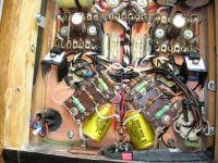
Just to clarify the rotary switches.
Not a good Idea to switch while its on!😀
Probably not needed..🙂 but there you go!
Regards
M. Gregg
Not a good Idea to switch while its on!😀
Probably not needed..🙂 but there you go!
Regards
M. Gregg
Attachments
Last edited:
In the RH design it can be to advantage as the higher output impedance is helpful to the Schade effect. In truth a Kitic effect as he described it after 50 years of not being discussed.
Its a bit controversial 😀
I must admit I don't know what to think about U/L that's why in the past all the amps were modified U/L-triode switchable even high power PPP amps. The feedback was always adjustable as well. I can never make a decision.
A FB adjust seems to give a sort of room tune ability to amps..
It stands out when you move the equipment to a different room and have to find the "Sweet spot again". Systems can sound bland when set to run at high volume and use it at low levels. Its a bit of a contradiction really when talking HIFI. In the old days you had the loudness control however its a quick fix that leaves much to be desired.
Regards
M. Gregg
I thought in the past UL the worst of all worlds. A nasal distortion for less power than pure pentode. Then I tried it without loop feedback. As far as I can tell used this way it works very well. GEC warn about problems in the 1972 GEC design book. No mystery as to cause ( 1000 watts + designs ). PP UL with loop feedback is not a nice problem to solve. I prefer transistor amps usually when that recipe suggested. GEC hint at cross coupling and ringing as the areas to check. Yet again the SE triumphs. Remember also a SE amp energizes the iron all of the time. No bad thing to do that. It means the iron can respond quickly as it never hits zero flux. I often wonder if MC pick ups are better when DC coupled to an amp with slight input offset current for the same reason. MM also I would guess.
One idea I came up with yesterday when driving the car is why not use 1000 V to the ECC81 (12BH7A when me). In my case 940 V as my HT is about 470 V before I filter it. There might be linearity gains. A chain of zener diodes to clamp at perhaps 350V with the valve defeating them when in use as protection ( maybe 160 V typical ). The 940V coming from a capacitor input voltage doubler that allows two supplies from one winding. If you don't follow the idea. 320 V - 160 V 3 mA = 56K 1 watt . 940 V - 160 V 3 mA = 820 K 10 watt. Nearest value up chosen. I am guessing 3 mA to be a good value.
The transistor CCS shows why it is an attractive idea , it's output impedance is even higher. The 820 K looks interesting as it is in paralleled with As the RH amps need the Rp to be very high Rp of the pentode looks best of all options. My RH amp never got to the very low distortion implied ( 5% at full power). That's why I went to pentode input. My final design 0.2% 1 watt all second harmonic and 1 % THD 6 to 8 watts. The latter with Hiraga style harmonic decay of distortion. Not bad for an amp with no loop feedback and full cathode regeneration (i.e. no local feedback).
Looking carefully at the 1000 V HT. In RH Rpt will be either 12 or 15 K ( 56 or 820 K ). That will not be of advantage. It is when conventional with lets say ECC82 that it looks worth a try. Transistor CCS should be tried ( ears ).
This below is the version I wasn't brave enough to build. The FET will almost be a pentode. Michael sometimes writes at DIY I think? Hope he doesn't mind sharing it. 5881 is much like most of the smaller devices such as KT66, EL 34, 6L6GC. It's RH meets Loftin white.
Did anyone try GU50( FU/LS) in the RH set up ? From what my eyes tell me GU50 is a EL34 type device with KT88 power.
Fitting the zener as in the dia is interesting. I have been warned it might cause unsuspected problems ( voltage doubling ). People forget a zener is a normal diode when forward biased. Some say isolating the g2 with a diode ( or beam plate ) this way improves sound. They believe it stops back EMF intruding. No idea if true. The guy who said it says the measurements do not change as they are not real measurements of music and a speaker. If triode strapped he would have a 1N4007 helping the 100R.
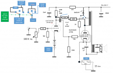
Just tried this,
Using a diode in the triode connection.
Its shown as U/L connected in the link , however if you don't try you won't know.
After reading this...well I had to give it a go..😀
Hiend Audio, DIY, Hi-Fi, Stereo, Electronics site, for lovers of high-fidelity music reproduction.
http://oestex.com/tubes/triode.htm
Early days lots of listening to do..🙂 and things to try.
I didn't bother about the tech explanations I just tried it.
Its in part 2 of the oestex.com link
Regards
M. Gregg
Attachments

Last edited:
This is good reading. If going RH route it suggests a simple way to help noise performance at the end of the text.
http://www.tubecad.com/march2001/2001_03.pdf
http://www.tubecad.com/march2001/2001_03.pdf
Just thinking,
In the oestex link they talk about PSU sag...
I never thought about it before..If the main PSU sags then the driver PSU will sag with it...they talk about protecting the driver supply..(never thought about it).. Wonder if it makes a difference..😕
All these diode mods are exploration.. ...if you don't try etc..
Regards
M. Gregg
In the oestex link they talk about PSU sag...
I never thought about it before..If the main PSU sags then the driver PSU will sag with it...they talk about protecting the driver supply..(never thought about it).. Wonder if it makes a difference..😕
All these diode mods are exploration..
...if you don't try etc..Regards
M. Gregg
I found the diode mod to clinical,
So its back as post 92# Triode.
(For the moment)😀 YMMV.
Regards
M. Gregg
So its back as post 92# Triode.
(For the moment)😀 YMMV.
Regards
M. Gregg
Last edited:
Just thinking,
In the oestex link they talk about PSU sag...
I never thought about it before..If the main PSU sags then the driver PSU will sag with it...they talk about protecting the driver supply..(never thought about it).. Wonder if it makes a difference..😕
All these diode mods are exploration..
Regards
M. Gregg
I think PSU sag is not a great problem when class A. Usually it is hum that is the big problem. DC heaters on the spectrum analyzer not the route to perfection people think. A hum bucked AC heater is hard to beat. The DC can do things at 100 (120 ) Hz that don't look as nice. A simple resistor should protect a PSU if it is needed. Avoid electronic protection as it is less good and can destroy speakers if it goes wrong. A resistor is best.
The TubeCad idea of strapping the EL 34 etc anode to cathode looks to be worth trying. That is to bootstrap the noise so as minimize it's effects.
I have been promoting the idea of a TR34 to JJ . I hope she tries it. The idea is to modify a JJ EL 34 to pure triode. It might resemble a PX25 at low cost. Fingers crossed as I do not have the money to do it myself. I said the g1 might need slightly changed geometry to get the best from it. The starting point is to not install g2 and g3 in the production stage.
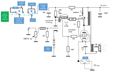
Just to update the thread,
Returning to this link:
Hiend Audio, DIY, Hi-Fi, Stereo, Electronics site, for lovers of high-fidelity music reproduction. High-End Vacuum Tubes. Silicon. Do-It-Yourself Audio Systems. Schematics: amplifiers, speakers, horns, CD, DAC. Circuits, Topologies, Acoustics, Cables
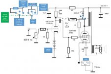
I wasn't happy with the diode enhanced triode..So its now connected in diode enhanced U/L (Switch position 2 with no RH feedback)..😀..I get restless at times..and have to try other things..Ive just added the pic for clarity. I am going to look into this a bit further. The next test will be replacing the 47K in the power rails with a diode to block discharge in the driver tube power rails (just to see what happens). Its the first time I've had chance to get back to it..😀 NB some sort of discharge would have to be used at power off for the PSU cap after the diode..however if you don't try it etc. LOL perhaps separate PSU for the driver stage. A bit overkill ?
Just reading this:
http://www.oestex.com/tubes/ul.html
Regards
M. Gregg
Returning to this link:
Hiend Audio, DIY, Hi-Fi, Stereo, Electronics site, for lovers of high-fidelity music reproduction. High-End Vacuum Tubes. Silicon. Do-It-Yourself Audio Systems. Schematics: amplifiers, speakers, horns, CD, DAC. Circuits, Topologies, Acoustics, Cables
I wasn't happy with the diode enhanced triode..So its now connected in diode enhanced U/L (Switch position 2 with no RH feedback)..😀..I get restless at times..and have to try other things..Ive just added the pic for clarity. I am going to look into this a bit further. The next test will be replacing the 47K in the power rails with a diode to block discharge in the driver tube power rails (just to see what happens). Its the first time I've had chance to get back to it..😀 NB some sort of discharge would have to be used at power off for the PSU cap after the diode..however if you don't try it etc. LOL perhaps separate PSU for the driver stage. A bit overkill ?
Just reading this:
http://www.oestex.com/tubes/ul.html
Regards
M. Gregg
Attachments

Last edited:
- Status
- Not open for further replies.
- Home
- Amplifiers
- Tubes / Valves
- Just a thought.