I read of a RIAA circuit using PCL 86. The input triode is basically a ECC 83 type at a different heater voltage. Looking around PCL 82 gets you better quality for the price asked. The idea is simple. The EL 84 like pentod has bags of current to drive the active EQ. The design almost looked like an RH idea. I think I saw Philips PCL 82 from Canada on eBay at £6.
My mind says 75 uS passive EQ using 75K and 1nF might be OK between triode and pentode and the 3180/318 uS active.
With RC smoothing it might even share it's PSU with the RH amps ( about 300 V ) . If so an ECL 82/4/6 might be better so as to share heater supplies. If being posh ECC 83 and EF 184 could be used.
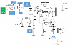
So here is whats being tested at the moment..😀
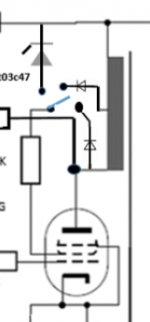
The 47K has been increased to 470K and bypassed with a diode.
The idea is the 470K gives a high resistance discharge path and the diode pulls up the driver supply.
Pick for fun..(sounds quite good at the moment)..as normal early days yet!
Just reading this:
http://www.oestex.com/tubes/oes.html
Obviously there is one diode and 470K on each driver (one per channel).
NB switch position 2 disconnects the RH feedback.
Regards
M. Gregg
Attachments
Last edited:
I read of a RIAA circuit using PCL 86. The input triode is basically a ECC 83 type at a different heater voltage. Looking around PCL 82 gets you better quality for the price asked. The idea is simple. The EL 84 like pentod has bags of current to drive the active EQ. The design almost looked like an RH idea. I think I saw Philips PCL 82 from Canada on eBay at £6.
Hi Nigel,
Do you know of a link to the circuit diagram?
Regards
M. Gregg

The input is for MC. Remove the transformer for MM. Someone said the designer obviously didn't know much!! All that it might need is a bit of improvement. If doing the 75 uS between triode and pentode the grid leak needs to be considered. I dare say it wouldn't be too difficult to work out ( make the resistor variable to have FFRR, NAB and RIAA, 78's). It could be active around the triode. That should be OK and preferable to where it is now. C2 looks a bit big? Hopefully someone would like to say where it should go from here. I guess that begs the obvious? Not bad for two valve packets.
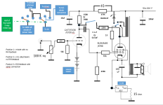
This is the position now after testing various ideas..
Position 1 is triode no RH feedback, position 2 is U/Linear (slipstream) no RH feedback, position 3 is RH feedback with zener...😀
Slipstream diodes are just 1N4007 both U/L and across the 470K ..you could try UF however in the past I have had High frequency problems..YMMV
Sounds very promising at the moment..😀
Regards
M. Gregg
Attachments
Last edited:
After some more testing,
I have replaced the 470K and diode with the 47K (as it was) the operating point is better..😀..YMMV
So for now I think it will stay for a while as last circuit (Post 106#)however with a 47K.🙂
Regards
M. Gregg
I have replaced the 470K and diode with the 47K (as it was) the operating point is better..😀..YMMV
So for now I think it will stay for a while as last circuit (Post 106#)however with a 47K.🙂
Regards
M. Gregg
Hi,
Why the input cap after the input xformer for starters?
I think the concept is viable, the execution however........
IIRC this circuit has been discussed on the forum.
Cheers, 😉
Someone said the designer obviously didn't know much!!
Why the input cap after the input xformer for starters?
I think the concept is viable, the execution however........
IIRC this circuit has been discussed on the forum.
Cheers, 😉
I wonder if the designer thought the grid shouldn't be loaded by a few ohms?
Myself I always direct couple and use a capacitor to the next stage. This brings some protection. If something silly happens usually gross distortion is the result. If careful that is the only cap up to the output.
As said before if passive 75 uS was used between triode and pentode I think this design is far from stupid. I very much like the idea of a pentode with 3180/318 in the feedback loop. Many birds killed with one stone.
Looking back to RH amp I found the thing I doubted was the ECC81 input valve. I tried substituting various triodes and found the argument revolved around gain. The designer was very insistent that all other ideas were wrong as he had considered them. Mostly I agree but not so much as to say it is a big deal. The fact the amplifier becomes conventional didn't bother me when using a GE 12BH7A ( Rp low so shunt feedback of EL 34 I to V converter reduced ) . I did try a cascode of ECC82 which I felt to be pointing to pentode. When I used a pentode I was happy. EF184 is a nice idea as it looks much like ECC81 when triode strapped. That means it can advance or stay as triode. If you think about it the distortion curve when pentode in triode out slightly works as a UL middle curve. That is the curves bend in opposite directions and the anti phasing of stages comes into it. I had 0.2% THD all second harmonic 1 watt. 1 % THD Hiraga preferred suspension bridge harmonics at 5 watts and slightly raised 3 rd at onset of clipping 8 watts. No loop feedback and no cathode degeneration. Input sensitivity 620 mV.
Looking at the RIAA stage my mind says what if RH style.
Back to RH. If EF 184 is used with shunt feedback it will use the same cap as the EL34 to input valve. That's nice. It might just be better? No one every thinks of shunt feedback as the other triode. As any pentode never becomes an absolute triode it is worth a thought. RH is triode by the less used route. The proof it works is damping factor is not bad.
Last edited:
After some more testing,
I have replaced the 470K and diode with the 47K (as it was) the operating point is better..😀..YMMV
So for now I think it will stay for a while as last circuit (Post 106#)however with a 47K.🙂
Regards
M. Gregg
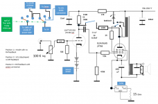
Just to remove any confusion. (How it stands now).
It was quite interesting..🙂 (I have a few things to try)
I will only post if I think its significantly better!
Regards
M. Gregg
Attachments
Back again,
100K from anode of output tube for the RH feedback increased from 100K to 150K. Component type is Takman metal film 1W...🙂
This gives a more usable balance in RH mode.(I had to post because it was an issue that needed resolving)
Regards
M. Gregg
100K from anode of output tube for the RH feedback increased from 100K to 150K. Component type is Takman metal film 1W...🙂
This gives a more usable balance in RH mode.(I had to post because it was an issue that needed resolving)
Regards
M. Gregg
Attachments

Last edited:
If wanting RH performance the ideal valve is ECC81 or perhaps EF184 even better. As Alex Kitic explained the Rp of that valve has to be very high to aid the shunt feedback . I would also use resistor bias to the ECC81 as it is unlike diode bias subtly. To be honest I don't see the attraction of diode bias when resistors do it so well and sometimes do it better. To realize Kitics ideal no cathode capacitor.
What EF184 might do is give lower and better distortion types and increase gain . My own version 620 mA for 8 watts.
What EF184 might do is give lower and better distortion types and increase gain . My own version 620 mA for 8 watts.
Just a bit more playing..😀
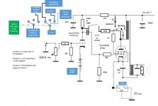
So I'm back to diode enhanced triode..
Switch positions are:
RH with Cathode FB
Slipstream diode U/L with cathode FB
Diode enhanced triode with cathode FB ....Yes I've gone back to it..
PSU mods are:
Choke bypass with reverse biased diode..rectification is now UF4007 with ceramic cap suppression. NTC in the negative rail after rectifier.
Nothing special..just an update and trying the electron stream mods..
Regards
M. Gregg
Attachments
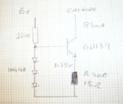
The HT seems to be 250 V and the current 83 mA. I guess at 18 watts anode dissipation ? I suspect you could run more current if you want. 100 ma should be fine at 12 R ( 11R LM317, 240 V is 27.3 W which is about OK ) . The LM317 has plenty of semiconductors, it is mostly a LM741 and pass transitor. Using a resistor should sound better. I can only guess at 330R 11 watt for that. 560 R when 60 mA and 450V HT. I know many use diodes to bias the input valves. I prefer resistors. This design seems to resemble the RH34. Did you reject ECC81 ? Kitic likes it as it works well in the Schade feedback so called. When I built similar I used HT 450 V. 5 K transformer and 63 mA. My input valve a pentode not unlike EF184. I did not use the Schade feedback in the end . The pentode helped the amp and improved on a triode. Triode is the easier route, not always the best. I could imagine an ECC 82 as cascode could work. Most other devices are less suitable. The second section a bit below 100 V usually to protect the cathode. I did build a transistor valve cascode. It worked as hoped for. It was transitor in ECC81 out. Sorry I lost my notes on that. The advantage being the transitor could allow the ECC81 to work near to it's ideal voltage as the transistor needed only a few volts. I think the ECC81 cathode was at +20 V.
My favoutie site.
The Valve Wizard
My favoutie site.
The Valve Wizard
I use the TL783 so I can just plug in EL34/6L6/KT66 etc
The driver tube is also either 81/82/83 etc
ie plug and play any output tube no bias setting.
The switch selector is for diode enhanced output selection with CF. Ie diodes on the UL and triode connection.
Just found out the old sketch PSU and put the mods on..😀
Its a play on a PYE Mozart/RH universal with electron stream mods.
Regards
M. Gregg
Attachments
Last edited:
Try the LED transistor version. 250 V transistors are cheap and very linear. T03P case also helps. You can take a power transistor to have a gain of 50 if 100 mA. You can easilly offer 25 mA to an LED. That should offer reliable bias. If not a double transistor CCS.
http://en.wikipedia.org/wiki/Current_source
I can see the reasoning behind the version of LM317 you use. There is also 317 HV . I am very careful of devices other than LM317. They can go unstable at the drop of a hat. Usually because the LDO versions use PNP pass devices where the collector drives the load. LD1084 is a very nice device if that 1.2 V matters. The same problem arrives if a PNP pass transisor is added to a LM317 or 7812 for example. LM317 will put many to shame. The ability to bootstrap its gain resistor gives very low noise.
Last edited:
I'll have a look at the alternatives to the LM317..
Its another thing to try out..🙂
I like being able to just plug in the driver and output tubes..mainly because I have a few different types...🙄😀 (fun project)
Regards
M. Gregg
Its another thing to try out..🙂
I like being able to just plug in the driver and output tubes..mainly because I have a few different types...🙄😀 (fun project)
Regards
M. Gregg
Last edited:

This is a bit of fun that works. I had much more than this. Alas I can not find it. You have to use cathode bias. The idea is to increase the bias when needed. I got 8 watts from an EL37 which can not give 5 watts usually. 1 nF seems about right. This is only for music. If sine wave testing don't do it for long if trying to avoid cherry red anodes. EL 34 will run rings arround KT88 using this. 1N4148 seems fine. It is very fast. The input was pentode. The EL 34 more linear but slightly more distortion.
I had loads of MRS 25 215 K. Use 220 K. Notice 0.1% THD at 1.6 W no loop feedback. 2 valves 620 mV in . EL 34 to the right. EL84 a typo.
Last edited:
Should have said 1uF for the previous vari-bias as in diagram. The 5 watt distortion looks more like a feedback amp. This is due to many factors. KT 88 itself is one of them. The pentode has a different distortion curve. Whilst reading 1940's ultra linear papers I realised the same would be true of a pentode input with triode output. It could do similar things as output ultra linear. Some would call this pre distortion. From trying maybe 15 pentodes of various makes and ages the distortion outcomes were very similar. Very old pentodes raised the THD by 50%.These were ones put to one side due to low emission. When all triode I had 5 % THD in a recomended circuit and hoplessly low senstivity.
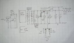
Here is something you might have a look at. I wanted to test a 211 driver circuit. The PP SE input EL 34's need 54 Vrms to drive them as the second valve is in grounded grid ( that is 2 x 27 V rms ). This mimics a 211 nicely. I tought the results rather interesting. At no point did this circuit give trouble. Notice the 1.25 V of the BD139 is the same as a LM317. I had just removed one. The FET will drive the HT if required. If so use the chassis to cool it. You will need a resistor before the FET as simple current protection if so. As it is a 12 A device make it 460/12= 39R 3 Watt ( 3 x 13R 1 W ideal ). If you don't fit it you wiill loose the FET, usually it takes a few switch ons to have it happen. If running 120 mA it will loose 5 V. This is a way of using all triode ( the 84 is strapped ) and have the sensetivity of a RH 34 amp. I suspect the sound of an SE amp with better bass control. The TF is a cheaper PP type. If you put in a 1 R resitor to each EL 34 cathode you can see if balance is the same. You should see about 60 mV each side. The 3 x 1N4148 has lower distortion than if 2 x 1N4148 and equals LM317. BD139 is 100 times faster than LM317 and MJE 350 is 6 times faster. The distortion might be due to Early effect in the transistor. The distortion is second harmonic so not too bad. BD139 can be a 250 V type in T03P if prefered.
BTW. If a valve specailist says FET better than transistor it will be untrue if a current amplifer in the audio band ( and long wave ). I use a FET here as at 500 V few transistors are usable.
As it is a sort of PP hum is resonable. If SE the FET is required. If - 82 db hum is OK the FET could be replaced with some RC filtering.
Tye 8 mA is a guess. The 10mA is what I wanted. Unlike LM317 some adjustment is required. Hence the 2 x 270 R. The cathode capacitor Panasonic FC type, use the higher voltage types for best sound. The PSU caps 2 x 680 uF ( 340 uF total ). The rectifier W08 with 56R 11 watt.
Notice I haven't added any caps to the current source/sinks to get better hum. Also no attempt to bootstrap the EL34 cathodes to ground. Wish I had as an extra graph is missing. The hum will be mostly as the raw DC is to the EL34 anodes. The PSU is from the SE amp. It was quickly made over for the test . I was to be paid for this. It never happened.
The 12 V zener to the FET is important. A 15 V type might be better. It works in both forward and reverse bias and will pass through the origine if required. It is also fast enough to work.
Last edited:
Interesting..
As you say same as Lm317.
The Valve Wizard
Just a quick scribble..🙂
I was just looking at your circuit its very interesting..
Did you find any problems with supply rail ripple with the BD139 circuit? (stability)
Regards
M. Gregg
As you say same as Lm317.
The Valve Wizard
Just a quick scribble..🙂
I was just looking at your circuit its very interesting..
Did you find any problems with supply rail ripple with the BD139 circuit? (stability)
Regards
M. Gregg
Attachments
Last edited:
- Status
- Not open for further replies.
- Home
- Amplifiers
- Tubes / Valves
- Just a thought.