Notice I haven't added any caps to the current source/sinks to get better hum. Also no attempt to bootstrap the EL34 cathodes to ground. Wish I had as an extra graph is missing. The hum will be mostly as the raw DC is to the EL34 anodes. The PSU is from the SE amp. It was quickly made over for the test .
What effect did you find with the above?
NB I don't think I would use CCS without fusing...🙂
Regards
M. Gregg
Last edited:
Interesting..
As you say same as Lm317.
The Valve Wizard
Just a quick scribble..🙂
I was just looking at your circuit its very interesting..
Did you find any problems with supply rail ripple with the BD139 circuit? (stability)
Regards
M. Gregg
I didn't really. I had a flight to get it to equal the LM317. As said 3 diodes seems to do it. I think what happens is at 2 diodes the transistor is too close to it's minimum working point. Early effect causes some second harmonic distortion. Ironic that a valve would show it. This was just comparing LM317 and BD139. The distortion was easy to spot.
Your version of LM317 is very interesting. About half the current but 125 V. The pass device is a DMOS FET. It is a sorce output if I am right. Strange it has lower loss than a 317. Noise performance is the same. Farnell have it at a good price.
What effect did you find with the above?
NB I don't think I would use CCS without fusing...🙂
Regards
M. Gregg
I really had no problems. The big surprise was the CCS. I abused it far beyond what I should. The valve below always rescued it. The sound was very good when it was used. Valves are very good voltage amps. A good CCS sounds mostly like a resistor. If Early effect is avoided almost a perfectly linear current amp. When fast devices it is hard to see how a choke could do better.
I can understand your caution. The 10 K resitor I show is also protection. If the CCS went short the valve was protected. I like cathode bias as it stops things going too far. Test your CCS first with a LED and PP3 battery. If it passes that test it should be OK. Hopefully no fake MJE340/350 out there ? I did try 3 x MPSA 92. The difference was small. I made the emitter resitor 3 times larger so as to share the current three ways ( 3 transistors and 3 resistors, collectors common ) . MPSA 92 is about 8 times faster and very cheap. Noted for it's linearity.
Here is the same cirucit with the EL 34's fed from the FET. Note the badly matched EL 34's and the very OK results. 0.2 % THD at 1 watt. And near perfect Jean Hiraga curves at 8 watts. 2 watts lost due to mismatch.

If wanting RH performance the ideal valve is ECC81 or perhaps EF184 even better. As Alex Kitic explained the Rp of that valve has to be very high to aid the shunt feedback .
The pentode signal tube is decidedly a better idea. The Schade FB thrives on pentode-ish output impedance. I didn't get this requirement at first when I developed the E-Linear circuit...but it eventually sunk in...🙂
cheers,
Douglas
If my understanding is right EF184 is almost exaclty an ECC81 when triode. As it goes to pentode the Rp is even higher and the distortion is complementary to the triode if in antiphase ( I call it east-west ultra linear ). Just when you think all the rabbits have come out of the hat the gain increases. As far as I know EF184 has no link with ECC81. It is happy accident it works. ECC82 is cascode is about the same. Alas it gives you nothing extra ( Rp will be high ). If a single ECC82 is placed in the RH 34 circuit it looses some of the I to V working. This actually helps the amp work very well. The trade off being gain. This is logical. The way I see it RH 34 etc is that a triode has been made as one might do with a transistor. That is the anode returned to the g1. This is as much a triode as strapping G2 I think. In returning the anode to g1 the input valve is in the mix. The higher the Rp of the driver valve the better the output pentode feedback will be. Kitic claims the Rp of his output valve at 900 ohm is better than the triode spec of 1k2. Maybe? That sort of says the feedback version is more triode than g2 strapping. That being true forget RH amps and just use shunt feedback.... I wonder ?
Some feed the signal onto EL 34 g2. I have the curves of that. It is a better triode. Hopeless gain if so.
I tried to get Josphina of JJ to make a TR34. That is a pure triode EL34. I think it would be a winner. If she isn't greedy she should sell tons. It should equal a PX25 and not need a special heater circuit. It's g1 would be in a slightly different place if getting the maximumm out of it. Between EL34 g1 g2 positions?
When the EF184 is used the same capaciitor that is a vital part of RH 34 can serve as input shunt feedback to the input valve ( see Valve Wizard ). How wonderful one part can do all the hard work of the amp.
The latest RH amps use a cathode follower to drive 300B or 813 . The same Schade feedback that seems to cope with the device of last resort the cathode follower. As far as I know the name Schade is to discredit the man Kitic. He was such a hot head when writting here and so reasonable when on his own site. He defended his amps as one might ones children. I don't think he understood that putting a ECC82 in doesn't make us stupid nor not understand his point. As many rightly said pentode would suit best. Michael Koster did a very nice version with FET as pentode input and 5881 output. It was DC coupled and worked a bit like my vari-bias in that it has both a cathode resistor and some positive grid bias.
If forced to used a cathode follower consider a transistor instead. It should be better. If a complentary feedback pair I am certain it would be. They have almost no sound if stable. If no loop feedback used they seldom give trouble. As near zero distortion as it easy to get. I am a purist so hate using any extra piece to do a job. If it must be used use the best piece.
Ignore this its just a thread update.
Just a quick update,
Ref post 115#
I am no longer using the reverse biased diode across the choke. (YMMV)
Diode enhanced triode is more acceptable with the UF diode bridge and ceramic cap suppression..
Regards
M. Gregg
Just a quick update,
Ref post 115#
I am no longer using the reverse biased diode across the choke. (YMMV)
Diode enhanced triode is more acceptable with the UF diode bridge and ceramic cap suppression..
Regards
M. Gregg
If an EZ80 was tried I guess the Va of 350 V will be too low ? Has anyone tried a EL 34 as a diode ? I priced Ruby at a very low price. EL 34 might be OK to 800V. I have never seen this done . Someone must have tried it. A friend uses a pentode as a series regulator. That gets close to being a diode.
Ruby EL34 Matched Power Tubes Quartet | Musician's Friend
Ruby EL34 Matched Power Tubes Quartet | Musician's Friend
I have seen EL34 used in PSUs.
We had some in a test lab for some time however I can't remember the name off hand.. used the EL34 as a variable regulator in a PSU HT test supply we had three of them.
Along with a pile of AVO8 😀..
Its strange I can't remember what they were called because they gave me two of them..I got fed up with falling over them so I took the Mullard EL34's out and threw the test supplies away..😀..They had Variable HT and a range of heater supplies including DC..Ah well. I could have at least taken the power Tx's out but no I didn't..They were quite good as I remember with a slow start and a large knob in the middle that set the voltage. (Quite old)
Regards
M. Gregg
Last edited:
I know of soft recovery diodes. Maybe the right choice ? These I suspect have optimum internal capacitance or whatever. The risk with external capacitance is a sharp very high frequency spike is turned into a series of lower frequency ripples that more easilly intrude into the AF band. The soft recovery diode seems to get it about right. The switch on is fast which is what you want. When the stored charge is allowed to dissepate it is at the right speed. In theory the biasing of the diode should make the use of a special diode not very important. This supposes the diode is a placebo and is doing nothing. Static measurements points that way. Maybe a better proof of the limited usefulness of static measurements? Not hard to see why. The back EMF of a speaker with real music will be unlike static measurements. Usually I don't think this way and accept static measurements as fine for spotting trends. This example says to me I should be careful and use my built in measuring devices, my ears.
BYV26D-TR - VISHAY GENERAL SEMICONDUCTOR - DIODE, ULTRAFAST, 1A, 800V | Farnell element14
BYV26D-TR - VISHAY GENERAL SEMICONDUCTOR - DIODE, ULTRAFAST, 1A, 800V | Farnell element14
I have some strange experiences with Fred diodes,
I have used them quite successfully in the past, however there is a difference with the UF diodes and ceramic suppression.
I have use BYV96e in the past as well, however the experience with the reverse biased diode used to bypass the supply choke seems to make the differences in the supply rectifier more pronounced. Which in itself is interesting when the site that suggests it says it removes commutation noise.
Its mentioned in section 7 in this link:
http://oestex.com/tubes/oes.html
Regards
M. Gregg
Last edited:
Opps..
Erratum
Post 115 obviously post 115# PTC is inrush NTC..oh well..sorry.
Its what happens sketching in a rush..
Regards
M. Gregg
Erratum
Post 115 obviously post 115# PTC is inrush NTC..oh well..sorry.
Its what happens sketching in a rush..
Regards
M. Gregg
Only barretter's in the past..
However the lamps are PTC
C1 @ The National Valve Museum
Inrush is NTC
http://en.wikipedia.org/wiki/Inrush_current_limiter
Regards
M. Gregg
However the lamps are PTC
C1 @ The National Valve Museum
Inrush is NTC
http://en.wikipedia.org/wiki/Inrush_current_limiter
Regards
M. Gregg
Last edited:
In the diode enhanced triode and the slipstream U/L,
I prefer the standard 1n4007..YMMV
 <<its a bit strange. It sounds more Triode if you know what I mean..😀
You would think the UF would be better..I haven't tried schottky...yet!
It doesn't make a lot of sense..I could understand reverse recovery etc..
The UF seems to have a bright edge that you shouldn't be able to hear..(No switching taking place?)
Perhaps Back EMF..
Regards
M. Gregg
I prefer the standard 1n4007..YMMV
<<its a bit strange. It sounds more Triode if you know what I mean..😀You would think the UF would be better..I haven't tried schottky...yet!
It doesn't make a lot of sense..I could understand reverse recovery etc..
The UF seems to have a bright edge that you shouldn't be able to hear..(No switching taking place?)
Perhaps Back EMF..
Regards
M. Gregg
Last edited:
Isn't it funny how cheapest can be best. I also use a lot of 1n4148 where I can. People forget how fast they are.
Isn't it funny how cheapest can be best. I also use a lot of 1n4148 where I can. People forget how fast they are.
Its interesting,
Many years ago everyone was saying about the UF diodes and the UF with soft recovery..so I bought a set of UF diodes to replace the ones in an amp I had built, and you could have stripped the wallpaper off the walls with the high end..this was also while trying bypassing the power tubes with reverse biased diodes to protect from Back EMF. Then Fred diodes seemed better.
The UL soft recovery seem better things like BYV96e...
In this application the 1n4007 sounds "Old school" I know its a cliché, however the sound is more like triode. The problem, is it switching noise or RFI in these situations..
There should be no reveres bias in theory..however there should be no back EMF in theory, however using toroid OP Tx's in the past there is an EMF issue..
Regards
M. Gregg
No idea if this would work? Farnell UK down so used USA.
C4D02120A - CREE - SIC SCHOTTKY DIODE, 5.9A, 1.2kV, TO-220 | Newark element14
C4D02120A - CREE - SIC SCHOTTKY DIODE, 5.9A, 1.2kV, TO-220 | Newark element14
Just ignore this its an update to a circuit resistor value,
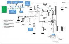
The Zener (BZT03C347)can be shorted out and that selection just used as Pentode.
Synergy for anyone interested.
Input 22K and 1M are 0.5W Tantalum magnetic.
150K 1 Watt Tantalum magnetic.
470K is 1W Takman MF.
10K is 0.5 Watt tantalum magnetic.
470K is standard MF 2 Watt 500V.
47K is standard MF 500V 2 Watt.
15 Ohm on CCS is Mills 5 Watt.
0.15uF is Audyn True copper.
Diode on U/L is 1n4007
Obviously don't switch while the amp is ON..but you already know that..🙂
Regards
M. Gregg
Attachments
Last edited:
I thought you might like to see this. Many who like the Kitic design never talk about distortion. Usually something about bass quality if lucky. This is why I gave up with it . It has high distortion and low sensetivity. I think I had 5 % at 8 watts. Using EL 34 was similar. The funny values are bunches of resistors at hand. On one Kitic thread 1 % THD and 14 watts stated. I have no idea how that could be true. The transformer here is Sowter so not causing the distortion. This wasn't done to show on this page and was for my interest. Many things were tried. This seemed about the best. At least the spectrum is nice albeit very high values ( even by zero feedback standards and SE ).

- Status
- Not open for further replies.
- Home
- Amplifiers
- Tubes / Valves
- Just a thought.