Halcro made a 'virtually distortionless' power amp. It sounded OK, but not great, and is not made anymore.
Benchmark makes one now, people rave about it. Boulder, Bryston, Halcro all the same story boring and clinical sound no PRAT, yawn. John do your Parasound amps fail if the load has 30 degrees of phase?
Last edited:
Where back-EMF is highest, impedance is highest too and phase shift=0 degrees. In other words, this is the operating point where a loudspeaker driver presents the easiest load to an amplifier.
Back EMF is scary. It goes right to the input of the amp through the primary feedback resistor. IIM distortion, if you are not careful.
What is scary about back EMF?
People believed certain trees housed evil spirits. The trees were real, the spirits not as progressing insights have revealed.
Back EMF increases impedance -clearly visible at resonance in plots - and any competently designed amplifier can handle the associated phase shifts as Scott mentioned.
Back EMF makes it easier on an amplifier. At resonance, you need the least amount of power to accelerate the cone.
😕 Anything else besides (speaker) placement? Because there are many more in the "to do list" of room acoustics.Unless stereo imaging is your thing, then room placement and even quality is not that important to hear differences in amp-speaker combinations.
Back EMF is both from the resonant frequencies AND any external room noise that goes backward into the speaker. Unless you have a NATURALLY LOW IMPEDANCE, without feedback, the feedback has to generate one in order to absorb the back voltage. It does this by changing the input to create an opposite voltage. Input stages distort and can overload on such signals. IIM folks, look it up! Triodes rule!
Last edited:
Input stages distort and can overload on such signals.
Right, clamp two speakers face to face and do the experiment you won't see much.
No, it doesn't contain any more or less. Will you folks please produce measurements for claims that relate to actual physically measurable quantities. I don't care about what your mates claim they hear.
Good luck on that request. It ain’t going to happen.
I measured it between two K-horns without any trouble.
They sound so colored in the first place why does it matter?
I'm still very curious about the very first inverse RIAA circuits. Right before the RIAA certified the circuit that RCA was cutting the New Orthophonic releases with, what exactly was that circuit built with? Was the main turnover points inductor based or were they RC based? Anyone know?
Right, for audio business.Oh BS! Listener feedback is all important!
Right before the RIAA certified the circuit that RCA was cutting the New Orthophonic releases with, what exactly was that circuit built with? Was the main turnover points inductor based or were they RC based?
Here's one example with both L and C.
http://www.preservationsound.com/wp-content/uploads/2010/11/RCA_MI-4916-A.pdf
I feel diagrams and some maths are needed here rather than thousands more words that would fail a turing test...
Agreed!
I did supply quite a bit of that earlier, showing an equivalence test (current versus voltage) that proved, and backed up by maths that variations in dBSPL is directly proportional to current.
Amplifier 6V, driver 8 Ohm with Re of 6 Ohm, hence I = 1A. That was then compared with a current source set also to I = 1A and the difference using a microphone measuring the dBSPL at 1M.
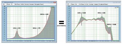
See attachment below. After I posted that and the associated numbers/maths that backed up those changes in dBSPL and that it proved 1) that the dBSPL is entirely proportional to current and not voltage and 2) that the back-EMF impedance is the impedance above Re (hence total impedance is always >Re) is a real impedance.
I then got the biggest laugh of the year when somebody here (I forget who, so he can be thankful) that "Just because it looks like an impedance, it doesn't mean that it is." I stitched over with laughter, so it is an impedance that is not an impedance? So 'he' was not as smart as he thought he was and 'he' was correcting me? What a hoot!
I also posted the maths concerning the motional impedance at Fs = 42Hz = 31R. But anybody with a calculator and a Log function can do that using the numbers in the equivalence test (you know the current, the voltage and the two parts of the impedance, you can repeat the same at 3KHz which is primarily back-EMF impedance cause by the inductance of the voice coil and same for 20KHz), this is not exactly rocket science, the numbers are clear.
I feel diagrams and some maths are needed here...
And you are right to ask for these.
I never denied that!
Not aiming this at you, but honestly, some of the protestations here ring rather hollow. When I did post "diagrams and maths" - I mean, look what happened. That just seemed to enrage even more.
Yes, the back-EMF of a driver is a voltage source and can be measured in Ohm, and yes it is an impedance because you can measure the degree (and calculate) because it impedes current (that is what an impedance does, it impedes current, not voltage). It looks like a duck because it is a duck!
But the back-EMF also being a voltage source, unlike Re it does not dissipate heat, the only heat that is being dissipated is across the Re, the DC resistance of the voice coil. Because the driver has a low efficiency of 0.5%, the dBSPL of the output (measured with a microphone) is also proportional within 1% to heat dissipation. So that is also a confirmation that the maths is 1% accurate. You have a nice correlation there and it is not a coincidence.
So it is both proportional to current and heat dissipated, but alas not the voltage. If some can't see that, then so be it.
So if anybody says I have not posted measurements and maths, then they are wrong - and what is more, I could have continued... but clearly the headwind against that reached, dare I say it, near hysteria? So that has prevented me.
So I have limited myself to sending a discussion paper to about twenty people around the world, and any analysis has been welcomed and accommodated one way or the other. There are always adjustments to be made.
BTW, that is called science and I have proceeded in a very conservative way. I would have loved to have engaged Pavel here, as I see that he has done measurements that I am familiar with, so I felt that there could have been some commonality there. But alas, seems that is not possible.
So there you are Bill, take a look below attachments, they were indeed posted before.
I have even decided to post clips of the maths regarding the three frequencies, but they are actually so straight-forward and can be repeated at any frequency and by any person, not just those three examples.
I live in hope eternal 🙂, and I am interested in anything constructive that you have to say. But nobody here is going to kill the topic, "sorry about that" as Maxwell Smart would say. 😀
Attachments

I'm still very curious about the very first inverse RIAA circuits. Right before the RIAA certified the circuit that RCA was cutting the New Orthophonic releases with, what exactly was that circuit built with? Was the main turnover points inductor based or were they RC based? Anyone know?
From what I have seen there were many inductor based equalizers.
Agreed!
I did supply quite a bit of that earlier, showing an equivalence test (current versus voltage) that proved, and backed up by maths that variations in dBSPL is directly proportional to current.
I just checked your web site it has plenty of measurements so you know what we are asking for, instead we get this verbal fountain of misdirection. What is the distortion of the acoustical output of your speakers with and without the shunt networks!!!
- Status
- Not open for further replies.
- Home
- Member Areas
- The Lounge
- John Curl's Blowtorch preamplifier part III