I wonder if we could set up a survey of cheap speakers to find the ones with the best linearity per dollar?
Well as in all speaker tests, the driver distortion is always lower than when listening. When I bring up the level to a modest 90db spl at 3 feet/ 1 m, the distortion goes way up compared to testing very close to the cone. To hear the bass, because of our loudness curve, we have to play a lot louder than for a tone a few inches away. When you are 3 m away, to get the same spl level, a lot more power is needed and thd goes way up fast.
The practical solution is to use larger cone area drivers for bass. Keeping the cone movement to a more limited excursion.
THx-RNMarsh
PS. since spkers for a car has the driver closer to you than in a living room... like 1-3 feet max, the cone size can be reduced and still have cone movement small enough to have low distortion.
A 6.5 inch diam might be OK for near-field listening in the home.
Last edited:
One man's modest is another's being driven out of the room. 😉 Unless 90db is peaks on some of the highest creat factor music out there.
(Just a friendly chuckle about how different our listening needs are.)
(Just a friendly chuckle about how different our listening needs are.)
If I am allowed to put my 12 cents, I would do this (as attached):
- measure THD (H2, H3) vs. frequency under standard voltage drive,
- measure THD (H2, H3) vs. frequency under current drive or with DVT correction, whatever you have available.
In my case, Beyma T2030 tweeter (resonance about 900Hz), we can see that H2 under voltage x current drive is almost unaffected. But, above 4kHz, there is a really dramatic decrease in H3 distortion for the current drive. This was shown in my previous twin-tone IMD measurements. So, if you make a H2/H3 vs. frequency, you may find where the distortion correction works and then make a FFT there.
What is the cause for the IM reduction? What is electrically/physically happening with "current drive"?
//
What is the cause for the IM reduction? What is electrically/physically happening with "current drive"?
//
If you look at IM plots and THD plots, IM distortion reduction is same as THD H3 reduction above 4kHz. IM FFT shows more spectral components, it is in fact odd harmonic reduction above 4kHz.
Electrically, everything in the current path (left side from the gyrator) is linearized. This is not true for the lumped components right from the gyrator. My guess is that for this tweeter the source of asymmetric distortion is the Kms, spider and surround stiffness. This cannot be corrected by the current drive, so it remains in the signal. Symmetrical distortion (enough above resonance) is corrected.
jneutron, do you know the relative permeability of a typical loudspeaker magnet? It's important for determining Bl(i) or reluctance force. Judging by some Le(x) measurements it's usually above 2.
After a few days I finally figured out the flux model. This allows me to model reluctance force, steel saturation, eddy currents, etc.
I have scrapped numerous schematics over more than a year and started over. If I knew of a better way, I would be doing it. If you really want to help, point out equations for Bl(v), Rms(v), Le(v) etc. These appear to be the distortions that don't fall into nonexistence as excursion decreases. All the distortions you mentioned respond to excursion which decreases with frequency, so if they were dominant then there would be no distortion above Fs.
After a few days I finally figured out the flux model. This allows me to model reluctance force, steel saturation, eddy currents, etc.
Let me ask a humble question, are we really concentrating on dominant speaker non-linearities? Please let me add 2 images from Klippel presentation and I would like to point to stiffness vs. displacement plot, e.g. and also the asymmetry of stiffness vs. displacement in tweeters (my yesterday measurements). Last, the speaker circuit diagram by Klippel ("gyrator stuff", as JN used to say).
I have scrapped numerous schematics over more than a year and started over. If I knew of a better way, I would be doing it. If you really want to help, point out equations for Bl(v), Rms(v), Le(v) etc. These appear to be the distortions that don't fall into nonexistence as excursion decreases. All the distortions you mentioned respond to excursion which decreases with frequency, so if they were dominant then there would be no distortion above Fs.
One man's modest is another's being driven out of the room. 😉 Unless 90db is peaks on some of the highest creat factor music out there.
(Just a friendly chuckle about how different our listening needs are.)
🙂 What exact level you enjoy at your listening distance has nothing at all to do with what I told.
-RNM
If you look at IM plots and THD plots, IM distortion reduction is same as THD H3 reduction above 4kHz. IM FFT shows more spectral components, it is in fact odd harmonic reduction above 4kHz.
Electrically, everything in the current path (left side from the gyrator) is linearized. This is not true for the lumped components right from the gyrator. My guess is that for this tweeter the source of asymmetric distortion is the Kms, spider and surround stiffness. This cannot be corrected by the current drive, so it remains in the signal. Symmetrical distortion (enough above resonance) is corrected.
May I interpret this as it is an amplifier improvement (left of gyrator) rather than something magic happens in the driver?
//
I understand that you can achieve some of the reduction by just adding a resistor in series - is it the same cause in this case?
//
//
A a rule of thumb you can't reduce distortion more than the number of times you multiply Re. So if you have an 8 ohm speaker and you add an 8 ohm resistor, you may get 6db distortion reduction. If it's 80 ohms, maybe 20db if you're lucky. Just depends on the speaker design.
That makes sense - thanks!
Still - I don't understand how the linearisation really work... please, someone?
//
Still - I don't understand how the linearisation really work... please, someone?
//
I have worked only with neo's, which are in the 1.05 range.jneutron, do you know the relative permeability of a typical loudspeaker magnet? It's important for determining Bl(i) or reluctance force. Judging by some Le(x) measurements it's usually above 2.
After a few days I finally figured out the flux model. This allows me to model reluctance force, steel saturation, eddy currents, etc.
I have scrapped numerous schematics over more than a year and started over. If I knew of a better way, I would be doing it. If you really want to help, point out equations for Bl(v), Rms(v), Le(v) etc. These appear to be the distortions that don't fall into nonexistence as excursion decreases. All the distortions you mentioned respond to excursion which decreases with frequency, so if they were dominant then there would be no distortion above Fs.
The path reluctance is dominated by neo reluctance. If a magnet has higher permeability, then it could be the gap dominating.
I'd have to google alinco or ferrite, never used them.
If the speaker is very non linear and you just connect the amp, the current draw will be dominated by the non linearity. If you put a thousand ohm resistor in series, the resistor will dominate, a thousand volts, one amp.That makes sense - thanks!
Still - I don't understand how the linearisation really work... please, someone?
//
A current source by design, has an infinite resistance so the current dominates. A voltage source by definition has zero series resistance.
Jn
JN: I think a more fundamental explanation is needed for those who are not living in this stuff. It may also help us get clarity in what we are trying to accomplish with all of this driver fiddling.If the speaker is very non linear and you just connect the amp, the current draw will be dominated by the non linearity. If you put a thousand ohm resistor in series, the resistor will dominate, a thousand volts, one amp.
A current source by design, has an infinite resistance so the current dominates. A voltage source by definition has zero series resistance.
Jn
Missing from the explanation I think is explaining that the driver motion is more proportional to the current than the voltage and the non-linearities from the nonuniform magnetic field affect the currents much less when the source is pure current rather than voltage.
With a voltage source driving a nonlinear load the non-lineararity manifests itself in the current waveform, it flips with a current source and the voltage waveform shows the nonlinearity. However the forces in the driver are current driven, not voltage (except electrostatic speakers. . .) so the motion should be more linear. However this does not help significant mechanical non-linearities from suspension or especially cone "breakup".
That makes sense - thanks!
Still - I don't understand how the linearisation really work... please, someone?
//
Speaker magnets are often called motors, and they behave similarly to electric motors. When you use your old hand drill, the speed stays fairly constant regardless of force (if it is a good one). This is because when the load is higher, the motor draws more current and gets more power from the input voltage. The reason this happens is that when the motor encounters no load, it produces it's own counter voltage which blocks the input voltage (commutation causes ripple, but don't let that confuse you about the basic relationship. The same applies for AC motors).
In speakers this is also true. The counter voltage (often called back-EMF or just EMF) is also not perfect. It contains extra nonlinearities that are often not present in the current-to-force function that is the primary mechanism of action. So the counter voltage adds these harmonics to the motor current, which are converted to force at the output.
With current drive, the counter voltage has no way to become a current (In an 8 ohm speaker, if the counter voltage is 1V, you will get 1V/8ohm less current. If your drive impedance is 1k, the loss in current will be much smaller, 1V/1008).
Of course now that the counter voltage is not regulating the motor, if you use current drive on your hand drill it's output force will be constant but it will go faster on light loads and slower on heavy loads. You would have difficulty controlling it.
In a speaker, the load is constant and more linear compared to a hand drill. The cone mass is the primary load above Fs and it never changes unlike the load on a hand drill. The box air load and spider are the main loads near Fs and they don't change much either unless you're driving the speaker hard. So what happens in current drive is you exchange load regulation for better motor force linearity knowing (ideally) that the regulation is less linear than the mass suspension system you are driving. Of course this is not always the case, speakers vary widely.
However the loss of regulation means the cone is not as well controlled across the frequency range. Speaker designers basically use coil resistance, inductance and eddy currents to adjust the speaker output to make it flat across the frequency range. With current drive all this tuning makes no difference, so you get very uneven frequency response, making most speakers useless without additional EQ designed for that speaker. At the same time the inductance and eddy currents would have been causing distortion, which is the compromise you have to make. Most current drive discussions are dominated by the desire for a solution to the EQ issue.
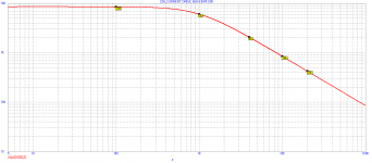
@RNMarsh: your post disappeared, however, I am posting a simulation of Zout of the amplifier that I use as a current output amplifier. Basically it is a VFB amplifier with Rf/Rg = 25k/1k. Output impedance reflects loopgain, or in other words openloop frequency response and Rf/Rg, not absolute values of Rf and Rg. Rf would be reflected if it was a CFB amp. But the output impedance reflects Rshunt as well (reference resistor)! The lower Rshunt, the lower Zout.
We can see that Zout is about 8.5kohm at 100Hz and 850ohm at 10kHz. Cut-off frequency about 1kHz.
We can see that Zout is about 8.5kohm at 100Hz and 850ohm at 10kHz. Cut-off frequency about 1kHz.
Attachments
Last edited:
1audio and keantoken, thanks for you explanations - I think I understand how it works now.
PMA - why didn't you make your amp low impedance in the bass and high in the treble? Wouldn't that make sense given where the bigger resonances are?
//
PMA - why didn't you make your amp low impedance in the bass and high in the treble? Wouldn't that make sense given where the bigger resonances are?
//
PMA - why didn't you make your amp low impedance in the bass and high in the treble? Wouldn't that make sense given where the bigger resonances are?
//
This amp's purpose was to check effect of current drive to distortion. The output impedance curve is Rshunt*loopgain.
Re your question, as explained by 1audio, keantoken and as stated on my webpage
Current drive of speakers and speaker distortion
there is an option of pre-filtering the input signal by inverse characteristics to impedance plot. This can be precisely and effectively done in rePhase - that's what I experimented with 4 years ago.
Thanks for the link!
Would you say it would make sense to make it low in the bass and high in the treble?
EQ these days should not be a problem.
//
Would you say it would make sense to make it low in the bass and high in the treble?
EQ these days should not be a problem.
//
PMA, on the last page you write "Or a steep HP filter cutting the low frequencies at the tweeter input."
Have you tried what happens if a capacitor is placed before the tweeter - do the IM suppression still appear? Maybe an active filter is better?
//
Have you tried what happens if a capacitor is placed before the tweeter - do the IM suppression still appear? Maybe an active filter is better?
//
I don't think it's too hard to make the impedance low at bass, maybe people just aren't sharing their experiments. The issue is that you can't make the impedance rise too fast, and this means it's a compromise. The area in between Fs and treble doesn't get as much of an effect as it would with pure current drive.
PMA, on the last page you write "Or a steep HP filter cutting the low frequencies at the tweeter input."
Have you tried what happens if a capacitor is placed before the tweeter - do the IM suppression still appear? Maybe an active filter is better?
//
I was thinking about active (or SW) filter, as current drive makes sense in active speakers, with active crossover on link level, analog or SW.
- Status
- Not open for further replies.
- Home
- Member Areas
- The Lounge
- John Curl's Blowtorch preamplifier part III