OK! "tweeter input" got me.
kean: "...you can't make the impedance rise too fast" - bugger... :-/
//
kean: "...you can't make the impedance rise too fast" - bugger... :-/
//
Other than the freq response looking like the Z of the speaker --- would the sensitivity or reduction in distortion be greatest with a VC ONLY in the place of the amplifier's Rf ? [with suitable Rg selected for mid freq gain] ?
Right now it is only a small addition to the amps Rf total value.
THx-RNM
Right now it is only a small addition to the amps Rf total value.
THx-RNM
I have worked only with neo's, which are in the 1.05 range.
The path reluctance is dominated by neo reluctance. If a magnet has higher permeability, then it could be the gap dominating.
I'd have to google alinco or ferrite, never used them.
I assume the gap dominates permeability. The reason I ask is it matters for finding the right numbers for the reluctance force. Unless the reluctance force can be known from the T/S parameters, but I don't know about that. Right now I'm assuming the magnet has enough H to produce Bl through the relative permability of the gap which I assume is somewhere above 2.
Other than the freq response looking like the Z of the speaker --- would the sensitivity or reduction in distortion be greatest with a VC ONLY in the place of the amplifier's Rf ? [with suitable Rg selected for mid freq gain] ?
Right now it is only a small addition to the amps Rf total value.
THx-RNM
It's interesting to see it this way. It's like the sense coil is being current-driven and the other coil is just along for the ride on the output voltage. I think it would be fine, as long as the coils were well coupled. I don't think it would be an improvement in distortion, probably just noise. Also the potential for blowing the amp's negative input with EMF surges.
But you also have the benefit that the sense coil is being driven at the same level as the other coil, minus 1/gain. This way you aren't wasting one coil.
The last part of your sentence..gap permeability is 1.(edit:unless ferrofluid is involved)I assume the gap dominates permeability. The reason I ask is it matters for finding the right numbers for the reluctance force. Unless the reluctance force can be known from the T/S parameters, but I don't know about that. Right now I'm assuming the magnet has enough H to produce Bl through the relative permability of the gap which I assume is somewhere above 2.
Has anybody measured a tweeter for intermodulation before and after the introduction of ferrofluid? In a dry gap, the gap permeability is 1, so eddy exclusion should decrease the permeability a bit, but if there is ferrofluid, it will drop more as the eddy exclusion causes the flux to go around the fluid. When I repaired one of my D205TI tweeters, I had to clean the gap out first, then load it with new fluid.
My prediction is that intermodulation would be higher with the fluid.
The reluctance will be a series circuit between the iron (assume zero), the magnet (area/thickness and mu), and the air gap (circumference times plate thickness over gap width).
I believe we have to consider an aluminum former as being a velocity dependent diamagnetic. As it moves, eddy currents will try to exclude magnetic field. The gap flux has to take a longer path around the former, which effectively increases the gap length and reduces the BL product. I suspect this is why there is intermodulation. This also means that even copper wires will have this effect.
The gauntlet of test has just reared its ugly head.
I have lots of neos, I can cobble together an iron loop with two gaps. I have a gauss meter in my office.
I propose making a complete magnetic circuit with neos as the drive, one gap to put the gauss meter in the flux of the loop, and a second gap to pass an aluminum plate through. I want to see the plate's eddy currents lower the meter reading.
Perhaps I will get to this before the new year..
Jn
Last edited:
How does this look? I was meaning the air dominates because it is harder to magnetize than anything else. But maybe it doesn't matter if the gap is small.
Since current modulates BL via reluctance, the amount of BL modulation we get depends on the reluctance/permeability of the motor. If I knew the reluctance, permeability (at as low a frequency as possible) or magnet H, I could pin it down. Estimating air inductance of voicecoil Le(x) graphs suggests permeabilty is above 2 which is the closest I got. But now I'm starting to suspect it's much higher than 2 and the Le(x) charts don't get near air inductance.
I have the eddy currents responding to absolute value of current. They also modulate BL, as any current in the flux loop would. But oddly enough none of the magnetic nonlinearities I've added are generating dominant 3rd harmonics.
Since this is probably the 3rd or 4th transformation of the model I haven't re-implemented Le(x) yet.
Attachments
Yep, current drive isn't happening at mid freqs with only an inductive slope of ouput impedance above Fs. One can use "over-inductive" slopes in a more elaborate feedback scheme to reach current-drive (Zout>10*Rdc) at a lower freqs but that is a bit sketchy. Better to start with a way overdamped driver (electrically) so that you don't need a very low Zout at Fs to establish a reasonable system Q of <= 3 or so because then you can shift the inductive slope much more to the right.I don't think it's too hard to make the impedance low at bass, maybe people just aren't sharing their experiments. The issue is that you can't make the impedance rise too fast, and this means it's a compromise. The area in between Fs and treble doesn't get as much of an effect as it would with pure current drive.
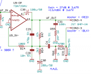
Attached is a scheme I once used in a product with ordinary small woofer with Qes ~ 0.4 or so, ported cab. Simple inductive slope starting at zero Ohms, HF stability (Zout peaks and gets capacitive above a certain freq), unity gain at DC.
Attachments
I have the eddy currents responding to absolute value of current. They also modulate BL, as any current in the flux loop would. But oddly enough none of the magnetic nonlinearities I've added are generating dominant 3rd harmonics.
Modeling the eddy current voltage as BL*v, I have V=I*v. In this case the BL source is moving and the current loop is still. Since coil current and therefore BL flips polarity every cycle, the resulting drag is asymmetric and tries to pull the cone off center. It is not odd harmonic dominant though. If I square I or V I get 3rd harmonics, but I need to tie it to a physical element in order for this to be a model and not just an equation.
One can use "over-inductive" slopes in a more elaborate feedback scheme to reach current-drive (Zout>10*Rdc) at a lower freqs but that is a bit sketchy.
I actually already knew about this, and you summarize my feelings. You would have to supply each amp with a stability contour plot just like chipregs and bypass capacitors.
Better to start with a way overdamped driver (electrically) so that you don't need a very low Zout at Fs to establish a reasonable system Q of <= 3 or so because then you can shift the inductive slope much more to the right.
An aperiodic enclosure doesn't sound that bad to me. What is the likelihood of an external damping method causing more distortion than the driver's own suspension? I've seen some speakers wrapped with cloth on the back.
Attached is a scheme I once used in a product with ordinary small woofer with Qes ~ 0.4 or so, ported cab. Simple inductive slope starting at zero Ohms, HF stability (Zout peaks and gets capacitive above a certain freq), unity gain at DC.
This is pretty similar to what I already have in simulation. What is R14 for?
Aperodic cone damping is best in my book also. As is a nice more linear spring force from a slightly dominating air spring of a closed box, no resistors here, please. But I can live with an underdamped, medium system Q or 1...3 as long as this is stable and linear mechanism. This helps to get closer to current drive properties at lower/medium frequencies. Below resonance, however, full damping (velocity-dominated drive down to the point until noise defeats its use) looks best to me as this at least partly avoids too much Cms(x) nonlinearities to enter. BL(x)*Cms(x) error is worse than BL(x) alone.An aperiodic enclosure doesn't sound that bad to me. What is the likelihood of an external damping method causing more distortion than the driver's own suspension? I've seen some speakers wrapped with cloth on the back.
Just a safety resistor.This is pretty similar to what I already have in simulation. What is R14 for?
EDIT: And, the compensation sure isn't SOTA ;-) and likey is a cause for trouble in a general-purpose amp with unknown load, cable capacitance etc.
Last edited:
Me in red.
Jn
I am going to have to really read all the Klipple stuff, as his "reluctance" stuff is more consistent with magnetic structures which move, like motors, solenoidal, and relays where the metal forming the magnetic path move. A speaker does not do that, so he used the IdL/dt term with somewhat unusual verbiage. Perhaps it's just a question of vernacular.How does this look? I was meaning the air dominates because it is harder to magnetize than anything else. But maybe it doesn't matter if the gap is small.air has a mu of 1. Neo mags run very close to 1. Ferrite and alinco, no idea. Iron, hundreds to thousands. So a neo speaker will not be as affected by an aluminum former BL wise because the magnets themselves dominate the reluctance path.
Since current modulates BL via reluctance, not sure what physical mechanism you are thinking of herethe amount of BL modulation we get depends on the reluctance/permeability of the motor. If I knew the reluctance, permeability (at as low a frequency as possible) or magnet H, I could pin it down. Estimating air inductance of voicecoil Le(x) graphs suggests permeabilty is above 2 which is the closest I got.infront of plate, it can drop towards air, but behind it the coil is connecting with the entire magnet structure. But now I'm starting to suspect it's much higher than 2 and the Le(x) charts don't get near air inductance.I suspect they cannot.
I have the eddy currents responding to absolute value of current. the eddy you currents in the former are velocity related, but they do not store energy, they dissipate and decrease the gap mu. The eddies in the iron near the coil will be frequency related and velocity related, a really ugly combination of both.They also modulate BL, as any current in the flux loop would. But oddly enough none of the magnetic nonlinearities I've added are generating dominant 3rd harmonics.
Since this is probably the 3rd or 4th transformation of the model I haven't re-implemented Le(x) yet.
Jn
I was referring to eddies in the pole piece or other parts of the magnet. The aluminum former hadn't crossed my mind since the current drive topic makes me want to avoid them.
It sounds like I neglected to model a second important flux loop, the flux loop of the coil which moves with it. This might fill in some puzzling blank areas in the model. This way the coil and magnet will both be modeled as complete magnetic systems.
I tried to come up with some Bl(x) functions today. I'm told Bl(x) is parabolic, but the only way I could get similar curves was with logarithms. I tried parabolic again with better luck, but it still has the same problem as the logarithms which is that the middle part of the Bl curve is waaaaaaay too linear.
BTW, I found this a year or two ago and still find it fascinating even though I don't understand most of it:
Surprises of the Faraday Cage
Last edited:
Me in red.
I am going to have to really read all the Klipple stuff, as his "reluctance" stuff is more consistent with magnetic structures which move, like motors, solenoidal, and relays where the metal forming the magnetic path move. A speaker does not do that, so he used the IdL/dt term with somewhat unusual verbiage. Perhaps it's just a question of vernacular.
Jn
I remember some years ago Professor Laithwaite of Imperial College London who looked into linear motors a lot came up with 168 different ways to do the magnetics for motors, that might take you off in a silly tangent, or it might help get things sorted. No idea how he arrived at the 168 number though.
A really fun demo.
The aluminum eddies cause flux exclusion, and the effect is strongest at the highest rate of change. The net effect as he said, is essentially a traveling wave.
This is consistent with shaded pole motors, where a shorting copper ring around some of the iron introduces a lag in the field the rotor sees, so it sets a preferred direction.
Of note in his vertical iron cylinder setup...I assume his coils were energized 50 hz. If it were DC, the rings would have floated down to the bottom.
1. Since its iron, the maximum fields the iron will support well is roughly 1.5 tesla. With only air as the flux return, fields will be less. Note that speaker gap fields I've looked at were 1.2 tesla, some higher.
2. The really thin foil didn't have sufficient eddies to support the rings, but the forces really picked up with thickness. These are the forces an aluminum former will have, but those forces will fight velocity in both directions.
I found this simple demo, but don't know how to grab the link to the you tube video using an IPad.
""Eddy currents and magnetic braking of a pendulum..""
Note he only used a pair of neo disks so the field wasn't even that big.
PMA, liked the literature links. The poster of non linearities was nice. Not complete, but very good.
Jn
Ah, also..the eddies in the rings are circular, so the currents are net circular.
Last edited:
Klippel talks as if there is no reluctance force if Le is constant. As far as I know this must be incorrect? Perhaps the coil is it's own additional source of reluctance force when EMF due to Le(x) gets converted back to current?
I have been assuming the i*v eddy currents in the pole piece have a structure the same as eddy currents in a pipe with a magnet falling through it:
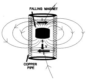
Doc Madhattan: A magnet falling in a metal tube
You have a band of current above and below both opposing the force of gravity on the magnet. Because the currents are in opposite directions they will cancel on axis, not contributing to net BL and not coupled to the coil, thus not correctable through the coil driving circuitry.
i*v(t) eddies have two ways of affecting the coil. The first is an opposing force resulting from modulated BL due to eddy currents, which changes the BLi force, which changes velocity. The change in velocity appears as EMF. The other way is dBL/dt induction causes an EMF proportional to acceleration which as I understand is the one that tends to stop a magnet dead in the air when dropped on a copper plate.
If I'm right this means the i*v eddies affect voltage drive through both velocity feedback and acceleration feedback (which impersonates an inductance d(i*v(t))/dt). I'm not sure yet to what degree they are corrected by voltage drive or not.
It makes sense why you want metal laminations and drilled holes; the laminations prevent off-axis eddies and the holes have the same effect for on-axis eddies (which themselves are coupled to the voicecoil and so potentially correctable).
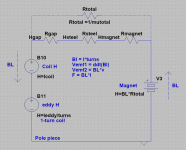
I've made a crude diagram of the flux circuits and eddies as I understand them.
One thing that keeps tripping me up is the difference between what happens when BL changes and when the BL is physically moving. I have to keep reminding myself that a physically moving BL does not directly cause eddy currents, rather a physically moving BL causes induced voltages, which then produce currents depending on conductivity.
I have been assuming the i*v eddy currents in the pole piece have a structure the same as eddy currents in a pipe with a magnet falling through it:
Doc Madhattan: A magnet falling in a metal tube
You have a band of current above and below both opposing the force of gravity on the magnet. Because the currents are in opposite directions they will cancel on axis, not contributing to net BL and not coupled to the coil, thus not correctable through the coil driving circuitry.
i*v(t) eddies have two ways of affecting the coil. The first is an opposing force resulting from modulated BL due to eddy currents, which changes the BLi force, which changes velocity. The change in velocity appears as EMF. The other way is dBL/dt induction causes an EMF proportional to acceleration which as I understand is the one that tends to stop a magnet dead in the air when dropped on a copper plate.
If I'm right this means the i*v eddies affect voltage drive through both velocity feedback and acceleration feedback (which impersonates an inductance d(i*v(t))/dt). I'm not sure yet to what degree they are corrected by voltage drive or not.
It makes sense why you want metal laminations and drilled holes; the laminations prevent off-axis eddies and the holes have the same effect for on-axis eddies (which themselves are coupled to the voicecoil and so potentially correctable).
I've made a crude diagram of the flux circuits and eddies as I understand them.
One thing that keeps tripping me up is the difference between what happens when BL changes and when the BL is physically moving. I have to keep reminding myself that a physically moving BL does not directly cause eddy currents, rather a physically moving BL causes induced voltages, which then produce currents depending on conductivity.
Attachments

Something to be investigated about speakers suspensions ?
YouTube
That would be terrible as a suspension, too much hysteresis. As I understand when the superconductor is repositioned, it saturates and then desaturates when let go. Otherwise it would never move.
Maybe something more like this:
YouTube
Too bad eddy current levitation is always so wasteful.
- Status
- Not open for further replies.
- Home
- Member Areas
- The Lounge
- John Curl's Blowtorch preamplifier part III