You are on the mark.. that comes from V = LdI/dt + I dL/dt.
I think that would be
V = Le*ddt(I(Le))+I(Le)*ddt(Le(x))/2
Whereas what I used was
V = ddt(I(Le)*sqrt(Le(x))*sqrt(Le))
or
flux = I * turns
turns = sqrt(Le)
My equation assumes flux changes linearly with turns whereas yours assumes flux changes linearly with inductance. I believe mine is correct? I suspect the first one is used for estimations since it is accurate for small signal analysis.
Last edited:
I was just using the equation for voltage, learned to back in '74. I just pointed out it's existence as a term. Kinda like "where babies come from" without being more specific.😀
Jn
Jn
Kinda like "where babies come from" without being more specific.😀
Jn
😀😀😀
Funny.
DVC drivers arrived to test.
-RNM
....There are no terms for defining eddy current parameters, so my only other guess is that it has to do with Le shedding stored energy as it increases and decreases. But if this is the case, then modeling Le modulation should provide the reluctance without the need for a separate model.
Eddy is a function of conductivity and rate of change of flux. So, it requires current, velocity, conductivity in the function.
For the former, the drag is a function of velocity. For the coils, it's a function of velocity, instantaneous current, and rate of change of current.
Le(x) is a consequence of the number of turns behind the front plate with some softening along the thickness of the plate. Behind the plate, the coils see the entire magnetic structure, in front they see air. I think a straight line function of x is reasonable.
It must be noted, with current drive, the amplifier does not know or care what the cone is doing, it is blind driving. If I lock the cone with my hand, the current drive remains the same. If there are large eddy losses, the forces will slow down the cone and the current drive will not see it. If I am dragging a hf in the coil past conductive surfaces using a lower frequency motion, the drag forces will be a complex function of everything including the kitchen sink.
In a voltage drive, if I hold the cone, the emf drops so current rises, it tries to compensate for the cone not doing what is expected. Eddies will make the current rise.
In my drive, if I hold the cone, Eddies will drop, as will Re total, so the drive will try to maintain voltage across a smaller R. But...emf will also change.
Tests will be interesting.
Jn
😀😀😀
Funny.
DVC drivers arrived to test.
-RNM
First, will try using the OmniMic system (Praxis) from Dayton Audio.
Other's also.
-RNM
... eddy current ....
In the case of a voicecoil the inductor EMF is responding to changing amp-turns. As the coil moves into the magnet, instead of changing current we are increasing the number of turns. As flux equals amp-turns and inductance is the square of turns, then
V(Le) = ddt(I(Le)*sqrt(Le(x))*sqrt(Le))
Where sqrt(Le) is just a static scaling factor to get the right inductance value. This behaves exactly like the flux inductor model in LTspice, but without the matrix solver glitches. I will see what the LTspice developer has to say.
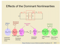
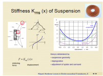
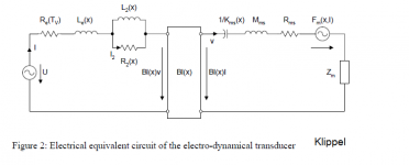
Let me ask a humble question, are we really concentrating on dominant speaker non-linearities? Please let me add 2 images from Klippel presentation and I would like to point to stiffness vs. displacement plot, e.g. and also the asymmetry of stiffness vs. displacement in tweeters (my yesterday measurements). Last, the speaker circuit diagram by Klippel ("gyrator stuff", as JN used to say).
Attachments

For members with limited work experience on E/M like me, your example could mean the drive helps and it could mean the opposite just as well. Since Re represents sum of losses in the system, an increasing loss means decreasing Re, the drive would then increase current to maintain voltage across Re in proportion to input. However, other distortion mechanism related to increase of Re (due to proximity for example) would need increased current to counter of which your drive will do the opposite. 😕... In my drive, if I hold the cone, Eddies will drop, as will Re total, so the drive will try to maintain voltage across a smaller R. But...emf will also change.
Tests will be interesting.
Jn
It is very difficult to understand what you see from the simplistic way of explanation. Humbly requesting your leniency to say a little bit more to follow what you are saying.
I just pointed out it's existence as a term. Kinda like "where babies come from" without being more specific.😀
Jn
Well, we know it always involves magnetic attraction and we can further develop the equation by considering stiffness (S), compliance (C) and maybe some element of reluctance (Rel). If encountering strong resistance (R), stiffness and compliance will tend to zero thus
Bby = (S + C)* kRel - R
Last edited:
I started to go over the different schemes response to external influences. One earlier statement by KSTR was on damping.For members with limited work experience on E/M like me, your example could mean the drive helps and it could mean the opposite just as well. Since Re represents sum of losses in the system, an increasing loss means decreasing Re, the drive would then increase current to maintain voltage across Re in proportion to input. However, other distortion mechanism related to increase of Re (due to proximity for example) would need increased current to counter of which your drive will do the opposite. 😕
It is very difficult to understand what you see from the simplistic way of explanation. Humbly requesting your leniency to say a little bit more to follow what you are saying.
I merely started to think out loud about the differences. We do not know in the long run yet if those differences will sound better or worse, or the engineering required to compensate for problems.
This all started because I came up with a way to pull the Re value out of an active coil in a complex magnetic environment without the need of computation, but instead,direct physical measurement. I realized that could be scaled down to an actual speaker. And the technique is useful for designing the magnetics as it provides a good diagnostic. Without a diagnostic, all you can do is theorize, model, and test an entity further down the chain. With smaller effects, you can come away from tests thinking the model is accurate when it may not.
It also dawned on me that if we can drive the dissipative elements with control, it might help the motion.
Eventually, all the losses and non linearities will be classed as local or global, with their effects and levels. Global meaning picked up by both coils equally Le(x) for example, local means affecting only one coil(IR drop, former eddy drag).
And, yes it is quite complex. I do not have all the answers, that is why I am here. For assistance with what I am weak in, as well as peer review of what I propose.
Jn
Let me ask a humble question, are we really concentrating on dominant speaker non-linearities? Please let me add 2 images from Klippel presentation and I would like to point to stiffness vs. displacement plot, e.g. and also the asymmetry of stiffness vs. displacement in tweeters (my yesterday measurements). Last, the speaker circuit diagram by Klippel ("gyrator stuff", as JN used to say).
I concentrate only on the magnetic non linearities and the resistive non linearities.
All the mechanical non-Lins are important, but I am concentrating on E/M.
My pickup scheme may be of assistance in diagnosing some of the mechanicals however.
I can even envision a system of using current drive for its good aspects, and the pickup coil as a second feedback signal to get the speaker even closer. As I said, current drive doesn't know or care what the cone is doing, the second coil may be able to help in that.
Jn
Or two amps, one for each coil, current drive above resonance, voltage drive around and below
Not the same but found this: https://www.diyaudio.com/forums/sol...rrent-drive-voltage-drive-lf.html#post5104855
Not the same but found this: https://www.diyaudio.com/forums/sol...rrent-drive-voltage-drive-lf.html#post5104855
Last edited:
Or two amps, one for each coil, current drive above resonance, voltage drive around and below
For the current amplifier, even if used above resonance, you need to add a filter that would have inverse frequency response to impedance frequency plot of the speaker - to keep flat frequency response.
I concentrate only on the magnetic non linearities and the resistive non linearities.
All the mechanical non-Lins are important, but I am concentrating on E/M.
OK, that is the explanation why we could not find a common view.
Not the same but found this: https://www.diyaudio.com/forums/sol...rrent-drive-voltage-drive-lf.html#post5104855
Quote: Originally Posted by MarcelvdG View Post
Decades ago there was an AES article about current drive combined with motional feedback that only worked around the resonance frequency. They used an extra voice coil as the sensor for the motional feedback. A long time ago, I did some experiments with that concept using a double-coil woofer (meant to be used as a subwoofer). It seemed to work well. You need to include a filter that compensates for the magnetic coupling between the coils, though.
I feel really grateful that software can do so many things quite well now.For the current amplifier, even if used above resonance, you need to add a filter that would have inverse frequency response to impedance frequency plot of the speaker - to keep flat frequency response.
Quote: Originally Posted by MarcelvdG View Post
I am sorry I will probably not go through that post, but I can say this: about 4 years ago I spent quite a few weeks with current drive of the box speaker. I made a SW filter in rePhase that was an inversion of the speaker impedance plot. The rePhase generated an impulse response that was used in a convolver plug-in of Foobar. So, you had a convolution of played music signal with the filter response. The thing worked quite well and it had the same frequency response as the voltage-driven speaker box. But the power was reduced as you needed an additional voltage swing at the power amp output to feed the current drive net reference resistor + the changes in frequency response due to the filter used.
I am sorry I will probably not go through that post,
That's ok, I'm not going to read through all the links, I just thought it might be of interest to some here
The former is correct (need to overcome the additional voltage drop accross the sense R, but normally this is neglegible -- about one volt or so -- when using a typical 0.1R...0.33R sense R). The latter is incorrect, we don't change the driver, thus for same SPL target the terminal voltage (and current) remains the same. The difference is at the amp input (and all the way back to the source, the output of your digital filter), though. The notch filter response might call for a somewhat higher headroom there for certain transient signals.But the power was reduced as you needed an additional voltage swing at the power amp output to feed the current drive net reference resistor + the changes in frequency response due to the filter used.
Yes, the filter transients==>bigger swing. I used higher resistor value, because it was a "standard" amplifier where just the feedback resistor was switched from amp output to speaker output and sub ohm values would thus result in enormous current. Re notch filter, it was not only a trivial notch, but it corrected for inductive impedance rise as well.
OK, that is the explanation why we could not find a common view.
That is very odd, what you say.
I have always known we share a common view. Perhaps a few minor details need hashing and clarification, but that is all..😉
jn
- Status
- Not open for further replies.
- Home
- Member Areas
- The Lounge
- John Curl's Blowtorch preamplifier part III