Hello all
It's been a while and you have been busy
Now I have to catch up from where I left off, now where are those boards ??
Miles
It's been a while and you have been busy
Now I have to catch up from where I left off, now where are those boards ??
Miles
I forgot all about doing this ...
I completely forgot about this version II thank you for reminding me.
Miles
And I have to wonder why no one actually built the complementary version (Circuit 2) :
The Class-A Amplifier Site - JLH Headphone Amplifiers
If anything, it is much simpler (ignore the circuit around Q3,4 which is just for bias stabilisation).
And it has less even harmonics.
Just because of lack of cheap PCBs ??
Patrick
I completely forgot about this version II thank you for reminding me.
Miles
Right then, I'm now up to date ..
Sadly lots of images are missing from older post's
My step by step build starts at post #114
The JHL Schematic is at post #119
The original schematic can be found here
The Class-A Amplifier Site - JLH Headphone Amplifiers
So outstanding issues - still an issue with DC offset maybe due to the supplied transistors in the kit which may be out of specification.
And oh joy someone is now making a finished PCB, does this still have the ground plan issue?
Or search for JHL Headphone Amplifier Finished Board
JHL Single-ended Class A Dual Channel Headphone AMP Amplifier Finished Board | eBay
How are people getting on with the finished board ?
Miles
What would that "issue with DC offset" be? You can't dial it in?So outstanding issues - still an issue with DC offset maybe due to the supplied transistors in the kit which may be out of specification.
The voltage between input transistor base and output is always going to be approx. 3 B-E drops or ~1.9 V, with the DC offset adjustment giving you approx. 0 ... -2.7 V for the input to compensate. The transistors could hardly be that far out of spec unless they're the wrong thing entirely (even if just wrong pinout), misplaced / rotated, or some other component is wrong (like one of the 4k7s R23/24/5/6).
One thing you need to be aware of is that adjustment will have to be fine-tuned once warmed up, B-E voltage drops being quite temperature dependent (negative TC, ca. -2 mV/K). The zener also has a negative TC though (ca -2 mV/K, reduced by 10k adjustment pot to ca. 2/3 of that).
Reports indicate that increasing 1k resistor R21/22 value to e.g. 3k3 actually reduces DC offset drift during warmup, so the original design may have been overcompensating by running the zener too hot entirely. If so desired, you can try determining the best value experimentally (though no doubt tediously) by using a single-turn 10k pot in place of the 1k, minding power dissipation. It will depend on both transistor heatsinking and zener type / wattage. If the one who put together the schematic is not the one who assembled the kit, chances are DC offset thermal stability won't be ideal.
If the problem is more severe, I'd say grab the multimeter and measure:
* +/- supply voltages
* voltages at E, B and C of every transistor on one channel
Do you have a component tester (e.g. AVR-Transistortester and its numerous Chinese offshoots)?
Last edited:
Your're back
Hi Miles
Welcome back. I found your earlier posts a great help when I built my JHL 1969. Your last post was #152 IIRC in July 2011. That's over 8 years ago ! What brings you back ?
Mark
Hello all
It's been a while and you have been busy
Now I have to catch up from where I left off, now where are those boards ??
Miles
Hi Miles
Welcome back. I found your earlier posts a great help when I built my JHL 1969. Your last post was #152 IIRC in July 2011. That's over 8 years ago ! What brings you back ?
Mark
??????????? ??1-003, ???????????-004, ?????-003, ?????-004, ?????-005 - ???????? 396
.
This is a fool project JHL Class A HedPhone Amp, see web link (Russian letters). (describe in Russian)
.
PDF documentation files.
PCAD2006 Binary files SCH and PCB.
Gerber files for China and Taiwan (total 8 files).
.
.
This is a fool project JHL Class A HedPhone Amp, see web link (Russian letters). (describe in Russian)
.
PDF documentation files.
PCAD2006 Binary files SCH and PCB.
Gerber files for China and Taiwan (total 8 files).
.
Attachments
-
JLH_Class_A_bottom_cooper.pcb.pdf135.9 KB · Views: 226
-
JLH_Class_A_top_cooper.pcb.pdf132.4 KB · Views: 247
-
JLH_Class_A_bottom.pcb.pdf33 KB · Views: 215
-
JLH_Class_A_top.pcb.pdf58.4 KB · Views: 254
-
JLH_Class_A.sch.pdf122.7 KB · Views: 345
-
JLH_Class_A_sch_pcb.zip806.6 KB · Views: 198
-
JLH_Class_A_gerber.zip269.1 KB · Views: 188
Last edited:
Hi,
I am a beginner in diy audio, and I bough this cheap board (And As well the ha-pro2) to start to learn something.
Aiyima JLH HOOD 1969 Class A Headphone Amplifier Small Power Amplifier Pre amp DIY KITS|class a headphone amplifier|headphone amplifierheadphone amplifier class a - AliExpress
I‘m waiting the delivery, and in the meanwhile I try to follow your indication in this forum. I didn’t understand a lot honestly, but I don’t want to burn my headphone at the first try .....
Could you give me the basic instructions to test the board before to connect the headphone(32Ohm)?
Which voltage I need to check, and where?? Which will be correct value?
Where I have to insert the cap to ‘protect’ my headphone? Is it mandatory, or I will burn it surely?
Is it mandatory invert the polarity of the 2 caps?
Thank you and sorry for the questions... that It could be stupid...but I try to do of my best 🙂
surfparadise
The best thing to do is to follow Miles Campbell's instructions from post 115 to 158. They include how to measure DC offset and how to minimise it.
He modified the design to minimise the DC offset by replacing the trim pots with a wire link and changing the resistors next to/near ? them.
I found it was better to change the resistors as he recommended but to leave the trim pots in and adjust them about an hour after switch on to give zero offset. That way the DC offset was approx 70mV at switch on, which dropped to less than 30mV in a minute and dropped to zero in less than 5 minutes.
surfparadise
The best thing to do is to follow Miles Campbell's instructions from post 115 to 158. They include how to measure DC offset and how to minimise it.
He modified the design to minimise the DC offset by replacing the trim pots with a wire link and changing the resistors next to/near ? them.
I found it was better to change the resistors as he recommended but to leave the trim pots in and adjust them about an hour after switch on to give zero offset. That way the DC offset was approx 70mV at switch on, which dropped to less than 30mV in a minute and dropped to zero in less than 5 minutes.
LOL...I don't care car if you follow Miles Campbell's or anyone else's directions here for lowering the DC offset of this particular amplifier.
Ultimately, you're going to have to deal with a WILDLY varying offset that can easily shoot up to a headphone frying 2VDC+ and is heavily dependent on the temperature of the output devices.
A servo is the ONLY way to keep the offset within a reasonable level of a millivolt or less.
Best of luck with trying to manage the offset without a servo.😀
Mercedese63
My amp has none of your problems and quick check using the link surfparadise provided shows it's the same pcb as mine.
If you have an amplifier with a WILDLY varying offset that can easily shoot up to 2VDC and is heavily dependent on the temperature of the output device then either you didn't build it properly, we aren't talking about the same amp or you didn't bother trying Mile Campbell's mods.
So, what do you suggest? Put it directly in the garbage?
Surfparadise,
I suggest you build it using the instructions Miles Campbell wrote in this thread that I pointed you to, taking the precautions he recommends.
Surfparadise,
I suggest you build it using the instructions Miles Campbell wrote in this thread that I pointed you to, taking the precautions he recommends.
👍🏻
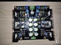
See attachments PDF file.
This is a circuit of JLH Class A HeadPhone amplifier.
.
The uploaded circuit diagram (pdf) and the PCB part number do not match.
Please upload a circuit with the same part number as the PCB plz.
The regulators would get rather toasty, though perhaps not unmanageably so... around 2.5 W may still be doable with these decently-sized heatsinks. Likewise, the 25 V rated cap should just about cope.
As a potential workaround, you can try some 15, 18, 20 or 22 ohm, 3 W dropper resistors in series with the secondaries. Those should take quite a bit of heat off the regulators. Mount with long legs as they will get hot.
Trimpots are likely to be for output DC offset adjustment.
As a potential workaround, you can try some 15, 18, 20 or 22 ohm, 3 W dropper resistors in series with the secondaries. Those should take quite a bit of heat off the regulators. Mount with long legs as they will get hot.
Trimpots are likely to be for output DC offset adjustment.
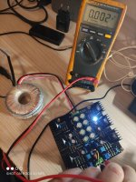
I finally got a +-12V toroidal. Heatsinks warmup takes around 10/15 mins: during that time I've been regulating several times the DC offset; after that time offset changes very slightly, in the order of couple of millivolts.
With a pair of Superlux HD668B (56 Ohms impedance) sound is excellent.
With a pair of Superlux HD668B (56 Ohms impedance) sound is excellent.
Attachments
- Home
- Amplifiers
- Headphone Systems
- JLH Headphone Amp