After extended listening last night and some more this morning (always important to do a listening-reality-check in the morning!), I'm going to say 80% of my complaints were addressed. This is a very nice sounding amp as it sits right now. And its strongest remaining coloration (some 'fatness' in the bass-lower mids) is not only "euphonic" and very kind to poor-quality recordings (of which there are many), it matches up very nicely with certain headphones, like the AKG K240DF's, which are a bit lightweight down there.
Also worth mentioning, the rendering of spatial info is really quite good. My "go-to" recording for a quick assessment of this is track 7 of Reference Recordings' Sampler Vol. 2 (an oldie but goodie). Not great music but a great recording. In order to balance the drums with the other instruments, they were intentionally placed some 15 feet behind them. This is most clearly obvious about halfway through, when the drummer settles into a "muted rimshot" pattern behind a solo. My speakers render this clear as day, but I've not heard it thru headphones as clearly as this. Even with the Senn HD580, which are not known to be space masters...
Thanks Mark. A tad pricey... but that's what happens when good things are discontinued.
Is there a runnerup to the 970?
Also worth mentioning, the rendering of spatial info is really quite good. My "go-to" recording for a quick assessment of this is track 7 of Reference Recordings' Sampler Vol. 2 (an oldie but goodie). Not great music but a great recording. In order to balance the drums with the other instruments, they were intentionally placed some 15 feet behind them. This is most clearly obvious about halfway through, when the drummer settles into a "muted rimshot" pattern behind a solo. My speakers render this clear as day, but I've not heard it thru headphones as clearly as this. Even with the Senn HD580, which are not known to be space masters...
B & D Enterprises of Russell, Pennsylvania has 2SA970BL in stock
Thanks Mark. A tad pricey... but that's what happens when good things are discontinued.
Is there a runnerup to the 970?
Last edited:
2SA1312BL.
But you need an adaptor and also watch dissipation.
Next best thing is 2SA733 or KSA733.
Also unibtanium but plenty on ebay.
Patrick
But you need an adaptor and also watch dissipation.
Next best thing is 2SA733 or KSA733.
Also unibtanium but plenty on ebay.
Patrick
2SA1312BL.
But you need an adaptor and also watch dissipation.
Thanks Patrick, looks like some wire-wrap wire could adapt those easily.
Heat dissipation an issue even on an input transistor?
10pcs New Double-Side SMD SOT23-3 to DIP SIP3 Adapter PCB Board DIY Converter | eBay
Much tidier.
I would not use the 2SA1312 for anything more than 50mW.
So it depends on the actual bias of your input stage.
Patrick
Much tidier.
I would not use the 2SA1312 for anything more than 50mW.
So it depends on the actual bias of your input stage.
Patrick
Watch out for non-NEC 2SA733s.
http://www.unisonic.com.tw/datasheet/2SA733.pdf
2SA1312BL is the better bet if bias is not more than 2mA.
Patrick
http://www.unisonic.com.tw/datasheet/2SA733.pdf
2SA1312BL is the better bet if bias is not more than 2mA.
Patrick
These are also not NEC, but CDIL :
2SA 733
SEGOR-electronics GmbH - Wir vor Ort - (Offnungszeiten)
Security Check
Rochester is for sure reliable :
Rochester Electronics (en-US)
: Search for 2sa733
Rochester Electronics (en-US)
: Search for ksa733
Patrick
2SA 733
SEGOR-electronics GmbH - Wir vor Ort - (Offnungszeiten)
Security Check
Rochester is for sure reliable :
Rochester Electronics (en-US)
: Search for 2sa733
Rochester Electronics (en-US)
: Search for ksa733
Patrick
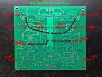
Aagh! I just realized that the picture I posted earlier with the cuts and jumpers to fix the hum problem was incomplete! The description was correct, but I forgot to show the changes for the regulator ground connections. A senior moment... my apologies.
The corrected pic is attached. BTW, the wires are shown curved only to avoid the other text. I would use as heavy gauge wire as you can tolerate for these reg gnd jumpers. I used 18. Oh, and insulate them, of course...
The corrected pic is attached. BTW, the wires are shown curved only to avoid the other text. I would use as heavy gauge wire as you can tolerate for these reg gnd jumpers. I used 18. Oh, and insulate them, of course...
Attachments
Last edited:
It turns out to be trivially easy to separate the signal and power ground paths on this board, and it's a very worthwhile mod. If there's interest, I'll show the changes.
After hearing the improvement the 2SD1020 made as a driver, I was anxious to hear what a better input transistor would do. I ordered some NEC 2SA733 that will be here Monday, but who wants to wait that long? I went back to the parts boxes hunting for suitable PNP's, and found 5 Toshiba 2SA1015-GR pulls. Two pairs matched up nicely at Hfe of 240. I installed them, readjusted the offset, and holy beans, what an amazing cleanup across the spectrum. This amp now sounds fantastic! Better than my 6120-based amp. I'll make some measurements in the next day or two.
I have no choice but to put my skepticism aside and am now a confirmed Class-A-ficcionado. At least at these low power levels.
It makes me wonder if Mr Hood ever had the chance to hear his creations with better transistors than the likes of the 2N3906, 2N1711, etc. he was using.
I am puzzled by one thing, however. The 1015's do not look as linear on the T1200 curve tracer as the 2907A it replaced. I'm new to using this thing so still not sure how to interpret it. Perhaps it is not testing at the proper levels for an input transistor.
Last edited:
There are also many different makes of 2SA1015.
So I've noticed. I see them on the input of the little 3W JLH boards I got last month. They don't look like the Toshiba parts.
The Toshiba 2SA1015 is just a low voltage version of the 2SA970.
So for most line level circuits just as good.
Interesting context, thanks. I also found a few Y grade. My notes say I pulled all of them several years ago from the input preamps of a scrapped Yokogawa chart recorder.
It was seeing the flat Hfe vs Ic curves in the data sheet that made me expect to see similarly flat lines on the curve tracer.
[/QUOTE]
I am actually somewhat surprised that you are not looking at other output devices.
One thing at a time... I had MJE15028G's in my Digikey cart, but they sold out... I did test the Hfe of these 41C's at 100 & 200mA and they looked good and matched perfectly...
For TO220, I use 2SC4883 2SA1859 (from DK).
For TO126, I use TTA004 TTC004 (both Mouser & DK).
Patrick
For TO126, I use TTA004 TTC004 (both Mouser & DK).
Patrick
I'll take a look at those. I still have a bunch of NPN TO220 and TO126 pulls to go through, I may find something nice there...
The main reason I like to work on two or more candidates at the same time is being able to apply what I've learned on one to the other right away, if it is applicable.
The TPA6120A board is back in the lead after doing so. Separating signal ground path from power ground was a complete PITA to do on this board. It was laid out with "ground plane" filling all non-trace space on top and bottom. But the bennies are worth it.
The TPA6120A board is back in the lead after doing so. Separating signal ground path from power ground was a complete PITA to do on this board. It was laid out with "ground plane" filling all non-trace space on top and bottom. But the bennies are worth it.
The JLH hp amp is now back in the running. There was still a 2N2907A in the current source position (Q5 in the original schematic, Q1 in the ZeroZone). I reason that current gain linearity is the most important parameter for that transistor, and even the 2N2907A's I had selected are not great at that. The most linear PNP's I have on hand are MPSA56. Putting those in made another across-the-spectrum improvement. Dynamics improved and everything sounds less thin and more "of a piece".
I hope to make distortion measurements later today. Gotta finish doing my taxes first 🙁
I hope to make distortion measurements later today. Gotta finish doing my taxes first 🙁
What is "current gain linearity"? Does that mean a graph of Beta versus collector current is darn close to a perfectly straight, perfectly horizontal line? I.e. "Beta is perfectly constant"?
Or perhaps does it mean that a graph of Beta versus collector current is a straight but not necessarily horizontal line? In other words, Beta = (Ic x nonzero_constant) + another_nonzero_constant
Or perhaps does it mean that a graph of Beta versus collector current is a straight but not necessarily horizontal line? In other words, Beta = (Ic x nonzero_constant) + another_nonzero_constant
What is "current gain linearity"?
My apology if I use the wrong terminology.
Does that mean a graph of Beta versus collector current is darn close to a perfectly straight, perfectly horizontal line? I.e. "Beta is perfectly constant"?
That's how I think of it..
Or perhaps does it mean that a graph of Beta versus collector current is a straight but not necessarily horizontal line? In other words, Beta = (Ic x nonzero_constant) + another_nonzero_constant
That doesn't qualify as linear in my definition. There are a lot of transistors that fit that description.
The only way I have to measure "current gain linearity" is with the little T1200 curve tracer, which is the same as the B&K 540 Component Tester. It has one range: base current incremented 100uA per sweep step, with Vce swept (up and down) 0-20V. The more linear Hfe devices have flat, equally-spaced lines that perfectly overlap on the up and down sweeps. The spacing between the lines is the current gain. I can post pics if you'd like.
It bugs me that the high-Hfe devices that are preferred on inputs (2SA1015, KSA733, etc) are only linear at the lowest current levels. This would argue for a higher source resistance than optimizing for noise would indicate. I have a Tek 7CT1N plugin that I plan on restoring and investigating this further with. It is more versatile than the T1200. No doubt this has already been looked into... if you know of this and can point me there, I'd appreciate it.
- Home
- Amplifiers
- Headphone Systems
- JLH Headphone Amp