Hi, Tiago!
There are no wires too thick - there are too thin ones 🙂
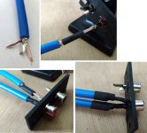
Use a shielded twisted pair cable for the input (you can use a cable for a computer network) or a shielded cable (microphone or television or interblock). Avoid an earth loop.
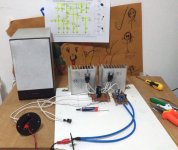
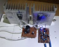
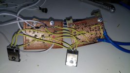
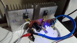
Hello OldDIY, I redid the project board. I eliminated that bunch of wires and joined them with smaller wires under the board. Q1 and Q2 have 9 cm wires up to the capacitor. I also placed the heat sinks vertically. I changed the audio input wires, I switched shielded microphone wires. The sound just got a lot better! I also changed the other 2 Transistors:
Q4 before: 2N2907 / current: BC560.
Q3 before: 2N1711 / current: BD139.
Circuit power supply: 19VDC
IQ = 1.1A
I will build another circuit to make it stereo.
Thanks for the tips and your time.
Att. Tiago Sierra🙂
Attachments
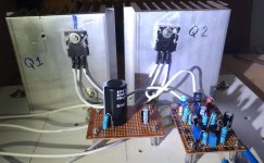
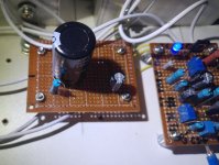
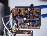
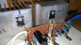
Hello Folks, I redid the project board again! I eliminated that bunch of wires and joined them with smaller wires (0.33mm) under the board. Q1 and Q2 have 5.5 cm wires up to the capacitor. I also changed the other 2 Transistors (again!):
Q4 before: BC560 / current: 2N2907.
Q3 before: BD139 / current: 2N1711.
Circuit power supply: 19VDC
IQ = 1.1A
Sounds Great!
I will make another similar circuit to leave the stereo sound.🙂
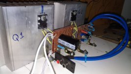
Q4 before: BC560 / current: 2N2907.
Q3 before: BD139 / current: 2N1711.
Circuit power supply: 19VDC
IQ = 1.1A
Sounds Great!
I will make another similar circuit to leave the stereo sound.🙂
Attachments
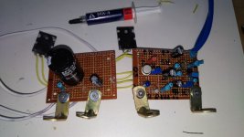
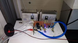
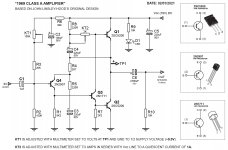
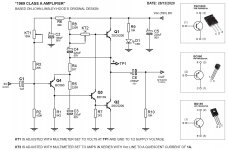
I deviated slightly from uncle John's amp but the results follows the looks. THD is absolutely monotonic and 0.064% at full output. BW is flat and extends to >100kHz and there is no oscillation even into 2.2uF
17.1V represemts the RMS voltage of the transformer under full load. Line ripple is 23mV after the cap multipliers. This info is just for interest and no claims are made. It sounds really nice, warm and vocals are very can I use the word natural?
17.1V represemts the RMS voltage of the transformer under full load. Line ripple is 23mV after the cap multipliers. This info is just for interest and no claims are made. It sounds really nice, warm and vocals are very can I use the word natural?
Attachments

Last edited:
There is zero hum or audible hiss even with HD800 connected directly on the output terminals. It is completely star wired.
Hello OldDIY. Whats about this twisting of cables? shielded ok! understand that! Why do people tell you to twist the high current cables to the main transistors? For me this doesn't make sense since this is a kind of spool and will add inductance? But maybe I miss something in my thoughts?
Twisting wires increases capacitance not inductance. The wire length controls inductance.

Wonderful to see revived interest in J. L-H.'s design and that it has stood the test of time.
Simple designs are often the best!
Simple designs are often the best!
P.S there were no wiki-leaks in 1976, so we had to rely on empirically by measurement and Smith Chart recorders. When a formula was not in existance we worked from first principles. The length of the wire will have an effect on the inductance but as Wiki may know capacitors also have intrinsic inductance, so has any length of wire coiled or straight. I still use this method to the day when I prototype RF equipment. And yes I am about 70 and some 50 years of electronic R&D behind me.
Hello all! Very nice thread (although I won't pretend to have read it all).
I have a selection of vintage RCA and Westinghouse 2N3055 and quite some time ago I decided the original JLH 1969 would be a fun way to use some of them. I am still researching at this point but I may begin building this amp in the next month or so.
Several times I have read the importance of using matched pairs for the outputs, or if that is not possible then use the higher gain part as Q1. Without a transistor tester, is there any way to fake my way through choosing transistors? I found a simple resistance test that can be performed with a multi-meter but that seems to merely confirm that the transistors will function.
Is it the case that Westinghouse 2N3055 was known to have lower (or higher) gain than RCA 2N3055? That would at least increase my odds of getting it right. I did read somewhere that the Westinghouse parts were lower-binned RCA parts purchased for cheap and re-branded by Westinghouse. The RCAs appear to be quite old (olde fashioned logo) - I am guessing 60s.
Maybe I am overthinking it?
Last edited:
Most multi-meters have an Hfe function on them.
Paid about £6 for mine on ebay and it works fine.
Paid about £6 for mine on ebay and it works fine.
Thanks Nigel. I'm out of luck on that one, but I've just found an excuse to buy another DMM. 🙂
multimeters cannot measure Hfe correctly for power transistors ( unless they have a completely "flat" curve hfe vs current ) ... because they do not have enough power.
Thanks Nigel. I'm out of luck on that one, but I've just found an excuse to buy another DMM. 🙂
1.Install the transistor on the heat sink
2.Take a power supply or 4-6v battery
3.Connect (-) batteries to the emitter
4.Connect a 470ohm resistor to the base, the other lead to the (+) battery
5.Connect a multimeter in current mode(10a) to collector and (+) battery. Write down the measurement number and current.
6. Take the next transistor (see 1)
At the end of the measurements, compare the obtained figures 🙂
Won't the same part numbers from the same manufacturer have approximately the same hFE vs. Ic curves?
If my goal is not to match, but only to determine which ones have greater gain than others, isn't a low power test accurate enough?
Anyway, I am glad to have an excuse to buy a tester. I bought this one, since I am happy with my basic DMM for other tasks. https://www.amazon.ca/gp/product/B084YRYXV5/
It is going to be very handy for quickly testing other components as well.
- Home
- Amplifiers
- Solid State
- JLH 10 Watt class A amplifier