why increase 10X capacity for all capacitors - what is the reason?
My jlh with 4700uf output and 2uf2 input provides approx. -1db at 20Hz (8 R load), how significant will the improvement with the 47,000uf capacitor at output ? IMHO waste of space and material..
My jlh with 4700uf output and 2uf2 input provides approx. -1db at 20Hz (8 R load), how significant will the improvement with the 47,000uf capacitor at output ? IMHO waste of space and material..
I have simulated and written about it before in this thread, so I don't plan on writing it all again. The problem with this thread however is to find the information.. It's up to everybody to make their own choices. Big caps are good for bass response.
Examples:
Output cap: will react with he impedance (resonance) of the woofer and alter the bass response. Try googling capacitor in series with woofer. Sometimes works in favor of a speakers response (small sealed box), sometimes not. It should be tuned to the speaker, or a really large value should be chosen.
Bootstrap cap: Low value will affect outputs current sharing at LF, decreasing efficiency and increasing distortion.
Input & feedback caps: Will affect phase of LF even if FR is almost flat.
All this can be simulated.
Yes I know that, but I doubt whether the phase shift at low frequencies can be heard by anyone-at least I don't hear it..
I clearly noticed the difference after trying lager caps, that is why I recommend it.
I believe everybody could hear the difference if the output cap causes a bad bass resonance with the woofers.
I believe everybody could hear the difference if the output cap causes a bad bass resonance with the woofers.
Q3 and Q4 - others components
Hello Rallyfinnen, I set up a circuit just like yours. but I didn't find the components Q3 (2N2907) and Q4 (2N1711). Can I use these instead: Q3 = BC559 and Q4 = BD139?
Thanks.
Att. Tiago Sierra
Referring to the attached schematic for the white board, you mean R8 and KT2?
So with a desired Iq the total resistance of these could be replaced with a potentiometer with this new resistance (let's say it exists in theory), and the wiper on the potentiometer connected to C4?
I'm I understanding you correctly?
So, the sweet spot I'm seeing is not due to the Iq (as I suspected) but due to the balance between the output transistors, cancelling the 2nd harmonic?
What I found most interesting with the measurements was the impact on the IMD, it was really a significant change.
2nd harmonic by itself I'm not so worried about, but in my experience, amps with high IMD (and a lot of high order harmonics) has always sounded harsh and flat (not much depth) to my ears. The impression is the same now when I listen to the white boards after the mod, the sound is significantly improved in mid and highs. Still the bass is a little bit muddy and 'soft', but not too bad.
I think the next step will be to try your sublimed version. I have the components already, so it's just a matter of getting it done. I think there will be some questions for you in that thread when I get started (have one in mind already about Iq adjustment)
Hello Rallyfinnen, I set up a circuit just like yours. but I didn't find the components Q3 (2N2907) and Q4 (2N1711). Can I use these instead: Q3 = BC559 and Q4 = BD139?
Thanks.
Att. Tiago Sierra
I cant remember this circuit, must be some time ago? At least I think the BD139 is not so good to use, I remember I had problems with high Cob using in other applications. BC559 could be ok.
Try to find something that is high Ft and low Cob I think. There is a lot written here, and a lot of circuits published. Have a look at those to see what transistor combinations have been successful.
Others will know more about transistor selection, so maybe they can give you some more advice.
I was never completely happy with the white boards when I compared them to the ZeroZone PNP version. That is the one I have used since.
From my experience, fast and linear beta output devices makes it sound (and measure) better, but also challenges stability, so the PCB layout and other transistors need to be up to the task.
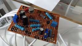
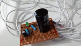
Hello guys, my name is Tiago Sierra, I'm 37 years old. I'm from Brazil. I'm an electronics hobbyist. I'm assembling my 1st JLH 1969 with DC 12V power supply. SONY speaker 4 "(6 ohms).
Follow the attached photos of the circuit and diagram. I still don't know for sure which IQ current: 1A? 0.5A? 1.25A? Can someone help me?
I would like to know if I need to change the transistors Q4 and Q3.
Q4: actual 2N2907. Or 2n3906, BC559, BC560, BC212 or 2SA970?
Q3: actual 2N1711. Or BD139 or 2SC3421?
Thanks.
Tiago Sierra
Attachments


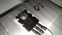
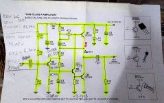
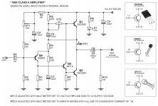
Tiago! Long wires Q1\Q2 - may be self-excited. At 12V, the current is 0.5-0.6A. Output power 2W / 6Ω. Transistor Q4 PNP, Q3 NPN general purpose TO-92. The pinout can be different - carefully. The input wires are separate. Better twisted pair or shielded.
Gold transistors won't give the best sound 🙂
Correct installation, correct positioning of wires, correct setting
Gold transistors won't give the best sound 🙂
Correct installation, correct positioning of wires, correct setting
Last edited:
Thanks OldDIY.
I'll put the IQ at 0.6A.
I will decrease the wire size of Q1 and Q2.
The audio input connector, I will put shielded cable then. 🙂
I'll put the IQ at 0.6A.
I will decrease the wire size of Q1 and Q2.
The audio input connector, I will put shielded cable then. 🙂
Audio Better!
Hi, OldDIY.
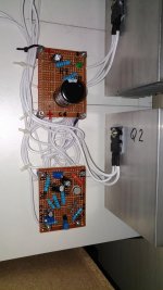
I shortened the wires, and organized better.
Sound is cleaner and much less hissing when it is muted.
I plugged the amplifier into a 19V DC source.
KT1 left with 1/2 = 9.5V
KT2 IQ? how much do I put the current? 1A?
Thanks.🙂
Tiago! Long wires Q1\Q2 - may be self-excited. At 12V, the current is 0.5-0.6A. Output power 2W / 6Ω. Transistor Q4 PNP, Q3 NPN general purpose TO-92. The pinout can be different - carefully. The input wires are separate. Better twisted pair or shielded.
Gold transistors won't give the best sound 🙂
Correct installation, correct positioning of wires, correct setting
Hi, OldDIY.
I shortened the wires, and organized better.
Sound is cleaner and much less hissing when it is muted.
I plugged the amplifier into a 19V DC source.
KT1 left with 1/2 = 9.5V
KT2 IQ? how much do I put the current? 1A?
Thanks.🙂
Attachments
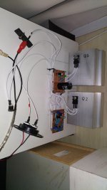
Hi, Tiago! Long wires Q1\Q2 - 10-15cm. Current 1-1,2A. Power 6W/6om.
It is better to place the radiator fins vertically. Raise the radiator slightly for better cooling.
It is better to place the radiator fins vertically. Raise the radiator slightly for better cooling.
Hi, Tiago! Long wires Q1\Q2 - 10-15cm. Current 1-1,2A. Power 6W/6om.
It is better to place the radiator fins vertically. Raise the radiator slightly for better cooling.
Hello OldDIY, I used 1.0mm wires in the circuit. Do you think the thread is too thick for this project? 19VDC (IQ 1A). (JLH 1969 / 10W)
Do you think it would work for me to use 0.33mm wire in the entire circuit?
Thanks.
Tiago Sierra
Hi, Tiago!
There are no wires too thick - there are too thin ones 🙂
Use a shielded twisted pair cable for the input (you can use a cable for a computer network) or a shielded cable (microphone or television or interblock). Avoid an earth loop.
There are no wires too thick - there are too thin ones 🙂
Use a shielded twisted pair cable for the input (you can use a cable for a computer network) or a shielded cable (microphone or television or interblock). Avoid an earth loop.
Last edited:
Hello OldDIY. Whats about this twisting of cables? shielded ok! understand that! Why do people tell you to twist the high current cables to the main transistors? For me this doesn't make sense since this is a kind of spool and will add inductance? But maybe I miss something in my thoughts?
Empiricism. May promote stability. May cause autogeneration. Short leads, short wires.
Last edited:
Twisted
The current will flow in opposite direction in the two wires, thus creating magnetic fields of opposite polaryties, which will therefore cancel, meaning less magnetic radiation.
Thorsten
Whats about this twisting of cables? shielded ok! understand that! Why do people tell you to twist the high current cables to the main transistors? For me this doesn't make sense since this is a kind of spool and will add inductance?
The current will flow in opposite direction in the two wires, thus creating magnetic fields of opposite polaryties, which will therefore cancel, meaning less magnetic radiation.
Thorsten
Hi, Tiago!
There are no wires too thick - there are too thin ones 🙂
Use a shielded twisted pair cable for the input (you can use a cable for a computer network) or a shielded cable (microphone or television or interblock). Avoid an earth loop.
Ok, thanks!!! I Will do this.
The current will flow in opposite direction in the two wires, thus creating magnetic fields of opposite polaryties, which will therefore cancel, meaning less magnetic radiation.
Thorsten
The magnetic fields are canceling out. Still they are existant. I think for the electromechanic force and the conversion of energy it is the same if it is one spool in a permanent magnetic field like in a speaker motor for example or if the magnetic field is created by the reversing current. In my understanding this would apply two times a loss through the Lorentz Force Effect.
Get the idea of twisted cables: What is the basic idea behind the twisted pair? Why are the two wires twisted? How does this arrangement compensate undesirable disturbances?
Don't know if it is a cure or creates another problem: Twisted-Pair Impedance Calculator - Electrical Engineering & Electronics Tools
Probably depends on the situation. Would prefer shielded. But I'm no expert. In any case I would avoid loops of cables inside the case
- Home
- Amplifiers
- Solid State
- JLH 10 Watt class A amplifier