I have built and sold on quite a few of the JLH 1996 versions.
They sound very sweet.
Found the basic circuit online then added recommended mods.

They sound very sweet.
Found the basic circuit online then added recommended mods.


Hi OldDIY,
That's a new PCB for the JLH 1996, I think and it and looks well designed. Do you have a link to the seller that you could post, if there is one?
That's a new PCB for the JLH 1996, I think and it and looks well designed. Do you have a link to the seller that you could post, if there is one?
Thanks guys, I appreciate your replies and suggestions. I have never built this version nor listened to it at home but I did audition a friend's stereo pair, built from hacked JLH'69 kits and playing through old but sensitive Celestion Ditton loudspeakers. As I remember, the sound was very good indeed. This was unexpected but you could never call it a serious comparison with anything.
Anyway, I think I'll order some boards and see if my memory still works - even if my ears aren't so great anymore 😉
Anyway, I think I'll order some boards and see if my memory still works - even if my ears aren't so great anymore 😉
Thank you Ian, OldDIY, John_Ellis for your opinions and advices! I've built the 2005 Geoff Moss version 4xMJ15003. I use these to power ribbon speakers (more or less similar to the Carver Ribbon 200-20000 Hz) with about 2,5 Ohms. Rail voltage is + 20 - 20 = 40 V and 4A / about 160 Watt heat 40 W per output transistor. Before I used the 69 JLH to drive the same speakers with 20V and 4 A and that worked the same (with only about 80 Watt heat). Probably with 2,5 Ohms resistance i guess that the current is the limit and not the Voltage. That means, higher voltage is just more excess heat.
Now I am planing to build bookshelf versions of this ribbon design which will have about 30cm heigt and will be about 1 Ohm. These are standing on the bookshelve, the sub on the floor below (F.A.S.T). The amps should be directly attached to the ribbons, no crossover or whatsoever in between.
(I want to avoid transformers, since they will affect transient response). It will be a prototype for further units, I want to keep it as simple as possible and then start to optimize the basic things voltage/ current, maybe feedback.., then component values part by part. I think the JLH design is simple enough to altern values and parts step by step and measure/ compare. I will start the project early jan, when I got two weeks for that, yet I've begun considering how to approach, order Stuff etc.
My Question: Does anyone know if there is a spice model of the 69 version, where to find it? Probably there is one, it is just so many posts, that I pretty much gave up searching!? I think this could save me a lot of time in experimenting!
Thanks again!
The problem with a low impedance speaker is that you need amps more than volts, but the increased current needs more drive power and/or output transistors.
the basic requirement is - what power do you need? then the volts=sqrt(PR) and amps=sqrt(P/R). 10W into 1 ohm therefore needs 3.16V and 3.16A rms.
You would best use transistors with high gain at high current, but quasi-saturation means having to use a higher voltage than ideal.
Note that in JLH's table, the distortion increases with reducing load. 1 ohm will be worse than the 3, assuming that the transistors you might use have gains of >100 as the ones JLH used (although modern devices should have better gain at higher currents, so will be rather better).
An output current of 4.5A peak (and that's only for 10W) will demand quite a high drive current, and may even need the driver to be doubled (Darlington or emitter follower boost), which will change the nature of the JLH original circuit.
But don't many ribbon speakers use matching transformers? You may be able to get Sowter to design/build an 8 -to-1 ohm high quality unit (but it won't be cheap.).
Possiblyy a JLH with MOSFEt outputs might be better placed for low impedances, but the low (depending on power needed) output voltage will still mean having to operate at a higher voltage than ideal - with a need for big heatsinks etc.
Main point - how much power do you need?
There are no barriers to supply 2005 from + _12v (or + -15v).
This will reduce the heat output at a higher current.
This will reduce the heat output at a higher current.
Right now I have completed this little but fine JLH project and, after fine tuning, this amplifier delivers quite a fine sound.
Actually, as I have later found out, the board I have used is an exact copy of Geoff Moss' 2005 design (well, with 2003 variation at R10). If you search this tread you may find Geoffs' post with complete documentation in a zip file.
The designer has included sections intended for PS decoupling and a filter consisting of a capacitor followed by a 10R resistor at the output. I have burnt that resistor twice while performing square wave testing at the maximum power and frequencies. These two features are quite fine and welcome addition. Without a signal on input you may hear just a graveyard silence at the speakers. Nothing, even with ears on the speakers. Like a dead amplifier - so fine it sounds, when silent. 😉
I have performed measurements with 22, 11, 7.3 and 5,5 ohm loads with +-24.5V rails.
I wouldn't change anything on this amplifier at least for two reasons:
1. it sounds great such as it is, after extensive tuning and testing of different components
2. it wouldn't be so kind to change anything on already historic design out of respect for many DIYers who have helped to develop this fine amplifier.
Sincere appreciation to all who have contributed to this fine thread 🙂

The problem with a low impedance speaker is that you need amps more than volts, but the increased current needs more drive power and/or output transistors.
the basic requirement is - what power do you need? then the volts=sqrt(PR) and amps=sqrt(P/R). 10W into 1 ohm therefore needs 3.16V and 3.16A rms.
You would best use transistors with high gain at high current, but quasi-saturation means having to use a higher voltage than ideal.
Note that in JLH's table, the distortion increases with reducing load. 1 ohm will be worse than the 3, assuming that the transistors you might use have gains of >100 as the ones JLH used (although modern devices should have better gain at higher currents, so will be rather better).
An output current of 4.5A peak (and that's only for 10W) will demand quite a high drive current, and may even need the driver to be doubled (Darlington or emitter follower boost), which will change the nature of the JLH original circuit.
But don't many ribbon speakers use matching transformers? You may be able to get Sowter to design/build an 8 -to-1 ohm high quality unit (but it won't be cheap.).
Possiblyy a JLH with MOSFEt outputs might be better placed for low impedances, but the low (depending on power needed) output voltage will still mean having to operate at a higher voltage than ideal - with a need for big heatsinks etc.
Main point - how much power do you need?
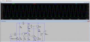
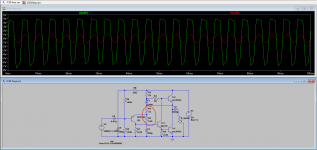
I've done a simple simulation in Spice. Just to visually check, if there is clipping on sine wave imput. red: V(in) +-0,3 V, green: V(out) +-3V, I(out) +-3,2, cyan: I(psu) ca. 4A.
Will build that and then measure if distortion is ok and if it is loud enough (though guess so!)
Attachments
hope that works for you!
Dissipation very high - at least 20W if not more in each OP tranny.
You may want to increase the output capacitor - your sim shows (sorry to use this phrase) "first cycle distortion" which is just a limited RC response and really more of an attenuation. Perhaps you don't need a particularly low LF response, but for 1 ohm I'd say at least 22mF normally.
You may find that high gain output trannys like MJL3281A a better solution in this case, they're OK up to about 4...5A, but may need some HF compensation.
#7514 BD139 for a plate radiator. A pair (or more) of output transistors in parallel. R3 = 1kΩ, R4 = 100Ω. LF=200Hz.
Last edited:
Parallelling transistors is not so simple though. You will need to add emitter resistors to make sure that the current is shared, perhaps 0.22 ohms to 0.33 ohms, depending on matching (perfectly matched devices might not need any - but then you need to make sure they are thermally equivalent too (same heatsink and mounting thermal resistances etc)).
The emitter resistors introduce additional voltage on the driver resistors (8.2k and 2.2k) which will increase distortion, so they need to be re-routed to the emitter of one of the lower output transistors (i.e. above the emitter resistor).
My guide for choosing the feedback resistor is to set the "grounding" resistor to the emitter impedance of the input transistor. Depending on the current, this is about 80 ohms in the original or perhaps 60 ohms for increased current with low bootstrap resistors. Suggest 56 or 68 ohms. The feedback resistor should then be 560 or 680 ohms or one notch up for higher gain. (Note that JLH's 220 ohms is way above and aids HF stability!)
As this will affect HF performance by increasing the input stage gain - this is not a "simple" change either. To benefit from the lower feedback chain you may need hf compensation once more.
If you can get the power and distortion you need from a single pair that would be my advice, but parallel and lowering distortion may need some tweaks.
Partly why I suggested MOSFET outputs as it seems you could (but I've not really explored this in detail) get the power and current you need - and a better frequency response.
Last edited:
JLH low impendance 1 Ohm Version
Reply: #7516, #7517: Thanks Old_DIY and John_Ellis. I calculate 20V*4A about 80W heat dissipation, mainly through Tr1 and Tr2. Means about 40W per Output Transistor. Thats the amount per OutputTransistor I got with my other JLH GM 2005 build prob. the max. which can be cooled with normal means. I want to avoid paralleling since it is much much easier to match 2 Transistors than 4, and also because of this thermal sharing problems which you mentioned. Also I want to avoid current sharing resistors, since they are already in the range of the speaker resistence and will themselves waste another lot of energy (and lost musical information?). Also want to avoid more parts etc. Want to keep the output Capacitor, to avoid any steady current running through the "ribbon". Want to keep the MJ15003 since I(max) = 20 Ampere and I was lucky and all I got had Hfe > 100.
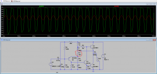
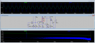
I will directly attach the amplifier to LineOut of the Soundcard, which has a max swing about little less than 2V. Compared to the last version I've again increased V(in) swing from +-0.3 to +-1V (supposed to be upper normal listening level). See Screenshots: First Clipping, then after adjusting R3, see reduction of voltage amplification and clipping. red: V(In), green V(out).
I just have basic understanding of electronics from school and know what the single parts do, but I can't get deeper into the complexity of the circuit (sadly!).
I've done this change on R3 / R4 just by testing. My idea was, that the bc560c should get less voltage and thus do less voltage amplification to pass over to the other transistors. I think this did increase Feedback? I think anyways it should work. Probably will build it this way!
Reply: #7516, #7517: Thanks Old_DIY and John_Ellis. I calculate 20V*4A about 80W heat dissipation, mainly through Tr1 and Tr2. Means about 40W per Output Transistor. Thats the amount per OutputTransistor I got with my other JLH GM 2005 build prob. the max. which can be cooled with normal means. I want to avoid paralleling since it is much much easier to match 2 Transistors than 4, and also because of this thermal sharing problems which you mentioned. Also I want to avoid current sharing resistors, since they are already in the range of the speaker resistence and will themselves waste another lot of energy (and lost musical information?). Also want to avoid more parts etc. Want to keep the output Capacitor, to avoid any steady current running through the "ribbon". Want to keep the MJ15003 since I(max) = 20 Ampere and I was lucky and all I got had Hfe > 100.
I will directly attach the amplifier to LineOut of the Soundcard, which has a max swing about little less than 2V. Compared to the last version I've again increased V(in) swing from +-0.3 to +-1V (supposed to be upper normal listening level). See Screenshots: First Clipping, then after adjusting R3, see reduction of voltage amplification and clipping. red: V(In), green V(out).
I just have basic understanding of electronics from school and know what the single parts do, but I can't get deeper into the complexity of the circuit (sadly!).
I've done this change on R3 / R4 just by testing. My idea was, that the bc560c should get less voltage and thus do less voltage amplification to pass over to the other transistors. I think this did increase Feedback? I think anyways it should work. Probably will build it this way!
Attachments

JLH low impendance 1 Ohm Version
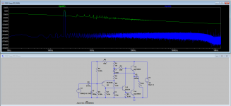
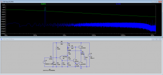
FF Post #7518: so far the simulation. Thought it was more difficult to use LtSpice: right click on the simulated traces: view -> FFT -> select V(in) V(out). Did further adjustment to R3. Anyway this tool helps a lot to try and investigate and make decisions. At least I can better understand which changes will affect the circuit in which way. Surely it will need some adjustments in the real setup depending on the actual values mainly of the transistors ..will see how close it got to reality!
FF Post #7518: so far the simulation. Thought it was more difficult to use LtSpice: right click on the simulated traces: view -> FFT -> select V(in) V(out). Did further adjustment to R3. Anyway this tool helps a lot to try and investigate and make decisions. At least I can better understand which changes will affect the circuit in which way. Surely it will need some adjustments in the real setup depending on the actual values mainly of the transistors ..will see how close it got to reality!
Attachments
Circuit DC JLH 1969 (with 2NSC5200)
Hello guys, I'm new here on the site.
I am looking to build a 1969 JLH amplifier - Class A.
I made an adaptation in this circuit.
Class-A JLH 1969 10W DC.pdf - Google Drive
I replaced the 2N3055 with 2SC5200. I didn't find these for sale, so I switched.
What do you think of the circuit? I found it on the internet and redid it in software.
Would you change any component, or change anything?
thanks.
Att. Tiago Sierra
All capacitance values x10 IMHO. If you make a PCB, add some pads for a compensation cap, in case it's not stable with the new outputs.
- Home
- Amplifiers
- Solid State
- JLH 10 Watt class A amplifier