Seems I got one of the last D200 Mk2, now they're sold out.
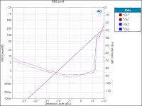
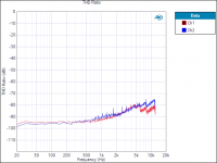
Any ways, here are some measurements on balanced (but admittedly a little wonky cabled) inputs. Measurements taken at 424mVrms as that is the point of lowest THD+N @ 1kHz. MeanWell LRS-350-48.
 Moderation edit. Quza has indicated an error in the attached images and has posted corrections below in a later post..
Any ways, here are some measurements on balanced (but admittedly a little wonky cabled) inputs. Measurements taken at 424mVrms as that is the point of lowest THD+N @ 1kHz. MeanWell LRS-350-48.
- Gain: 21.6dB
- SNR: 94.5dB
- SMPTE: -81dB
- Multitone TD+N: -75dB
- Maximum Output IEC 60268-3, 4Ohm: 90W @0.1, 115W @1.0
- Maximum Output CEA-2006, 4Ohm: 92W @0.1, 117W @1.0
- Maximum Output IEC 60268-3, 8Ohm: 48W @0.1, 59W @1.0
- Maximumt Output CEA-2006, 8Ohm: 48W @0.1, 60W @1.0
Moderation edit. Quza has indicated an error in the attached images and has posted corrections below in a later post..Attachments
Last edited by a moderator:
Curse you! 😡😀
Can't tell, I didn't find any information on how to do that. I only connected the solder bridges for balanced inputs and immediately hooked it up to the measurement rig. There were some jumpers in front of the heat sink, though.
Can't tell, I didn't find any information on how to do that. I only connected the solder bridges for balanced inputs and immediately hooked it up to the measurement rig. There were some jumpers in front of the heat sink, though.
Hah! Thanks! I just double checked the listing for the D200 MKII's, answered my question.
The board has a standard PFFB configuration from SLAA788A. PFFB is disabled by default and can be enabled/disabled through onboard jumpers (power supply should be fully turned off).
Hello Quza 🙂
It seems to me that there must be a problem with your measurements or at least concerning your assembly because we are very far from those communicated in Audio Scien Review with Lester's device which, as a reminder, was not even optimized 😗
I'm waiting for Lester and yourself to react to this because there must necessarily be something to work on 🤔
Sincerely.
D
Deleted member 148505
Sylph-D200 MKII uses the standard PFFB values for TPA3255 from SLAA788A, as opposed to the one on ASR, which uses the PFFB network for TPA3251. So it should get less SINAD because of less negative feedback.It seems to me that there must be a problem with your measurements or at least concerning your assembly because we are very far from those communicated in Audio Scien Review with Lester's device which, as a reminder, was not even optimized
My SINAD measurement for Sylph-D200 MKII is around 92dB @5W 4ohms. Sylph-D400M is better at around 94dB.
Onset of clipping on Sylph-D200 PFFB enabled is around 144W if a 48V power supply is used. PBTL version Sylph-D400 gets better output at around 200W on the onset of clipping.
Not sure why the gain measured was 21.6dB. Is this with balanced or SE input? For SE input, the gain should be 16.67x or around 24.4dB, or 18.4dB for balanced input.
Jumpers attached between the heatsink and input coupling caps is for PFFB enabled.There were some jumpers in front of the heat sink, though.
Regards,
Lester

Hello Lester, thank you for your clarification 😉
Quza, it would be necessary to show us (please) a photo of the wiring of your input, its diagram as well as the OPAMP used: it would be good too.
1> At first, do not change anything and activate the PFFB and redo your measurements ->

2> In a second step, carry out the modification (MOD) specified by Lester and redo your measurements again ->


However, check if your PCB does not have this modification already made:
you must obtain 200pF to 250pF between pins 1-2 and 6-7 on each OPAMP for this MOD to be effective 🙂
You should see improvements with each change 😎
Regards.
Quza, it would be necessary to show us (please) a photo of the wiring of your input, its diagram as well as the OPAMP used: it would be good too.
1> At first, do not change anything and activate the PFFB and redo your measurements ->
2> In a second step, carry out the modification (MOD) specified by Lester and redo your measurements again ->
However, check if your PCB does not have this modification already made:
you must obtain 200pF to 250pF between pins 1-2 and 6-7 on each OPAMP for this MOD to be effective 🙂
You should see improvements with each change 😎
Regards.
D
Deleted member 148505
I think his module already has PFFB enabled and has additional 100pF on the opamp pins.
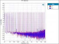
Last THD graph looks correct since 1kHz has around 90-95dB on it, maybe a variation on the quality of resistor dummy load will slightly affect the result of the measurements.
Last THD graph looks correct since 1kHz has around 90-95dB on it, maybe a variation on the quality of resistor dummy load will slightly affect the result of the measurements.
Hello Lester,
you're probably right but it will allow him to check 😉
If the modification is effective and represents well 200pF between the pins of the OPAMP, it seems to me that the correction is too important:
it would perhaps be necessary to put another value 🤔

It would still be interesting to know the OPAMP used and its 'action' on the PCB measurements.
you're probably right but it will allow him to check 😉
If the modification is effective and represents well 200pF between the pins of the OPAMP, it seems to me that the correction is too important:
it would perhaps be necessary to put another value 🤔
It would still be interesting to know the OPAMP used and its 'action' on the PCB measurements.
I had 91.8 on one channel and 94.5 on the other. Underspeccing is for work only 😉 I'll check the gain again next week, but the test setup was pretty much the same like I've used it hundreds of times: XLR outputs from generator to amp, speakon to shunt, XLR from aux-025 filter to analyzer. I don't see much potential for error.My SINAD measurement for Sylph-D200 MKII is around 92dB @5W 4ohms. Sylph-D400M is better at around 94dB.
D
Deleted member 148505
Sylph-D200 MKII with modified PFFB values
Same setup as previous post except that the power supply used is LRS-350-36 set to 41VDC.
5W 4ohms Left

5W 4 ohms right

Same setup as previous post except that the power supply used is LRS-350-36 set to 41VDC.
5W 4ohms Left
5W 4 ohms right
Hello Lester,
Great 😉
Can you do a test with 48VDC and 8 Ohm load ?
What does it bring if we leave the original input with OPA1656 OPAMPs in XLR input configuration ?
Great 😉
Can you do a test with 48VDC and 8 Ohm load ?
What does it bring if we leave the original input with OPA1656 OPAMPs in XLR input configuration ?
D
Deleted member 148505
Hello JLesterP,
Very good measures, indeed 😎
On the SYLPH D200 MKII PCB:
1> Can you perform a test with a film type capacitor of 10 or 15 nF (or other) in parallel with each PVDD capacitor to see their influence on the measurements ?
(I think it might bring 'something' interesting...)
2> Similarly, by replacing the 2 PVDD capacitors with others that have a lower ESR, an improvement should be visible on the measurements (example: United Chemi-con KYB 1200µF/63V with ESR=20MΩ, Ripple=3A replaced by Rubycon ZLJ 2200µF/63V with ESR=15MΩ, Ripple=4,1A).
3> The same could be achieved with the replacement of the two 100µF/25V PANASONIC FC (ESR=0,350Ω, Ripple=290mA) capacitors located under the PCB with PANASONIC FR (ESR= 0,130Ω, Ripple=455mA) ones.
The replacements that I propose are simple to make since these modifications involve capacitors with radial wires that are very simple to solder 😉
Cordially.
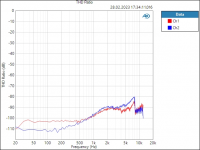
Turns out there was no problem with my measurement setup, but with setting up the amp itself. I used balanced inputs so I connected the solder jumpers for that - but I didn't desolder the single ended solder jumpers.
So here's new measurements, now also with twisted cables all around:


I only have one DAC that can put out +12dBu, my DSPs can't do that, so I will not be modifying the amp. I'd be very happy if Lester decided to make DSP boards that can feed his amps, too. 4 in, 10 out, please. 😀
PS: Gain is probably higher by 0.3 to 0.4dB. My cables and filters have -0.4dB when connected as loopback.
So here's new measurements, now also with twisted cables all around:
- Gain: 18.1dB
- THD+N @1kHz,+4.7dBu: -96dB
- SNR: 103dB
- SMPTE: -88dB
- Multitone TD+N: -75dB
- Maximum Output IEC 60268-3, 4Ohm: 141W @0.1, 165W @1.0
- Maximum Output CEA-2006, 4Ohm: 147W @0.1, 165W @1.0
- Maximum Output IEC 60268-3, 8Ohm: 79W @0.1, 90W @1.0
- Maximum Output CEA-2006, 8Ohm: 80W @0.1, 90W @1.0
I only have one DAC that can put out +12dBu, my DSPs can't do that, so I will not be modifying the amp. I'd be very happy if Lester decided to make DSP boards that can feed his amps, too. 4 in, 10 out, please. 😀
PS: Gain is probably higher by 0.3 to 0.4dB. My cables and filters have -0.4dB when connected as loopback.
Attachments
Hello Quza,
It's already much better 🙂
Like what details were needed 😉
Personally, I haven't quite finished my amp, which I will not fail to present first with a few details, then the measurements will follow as soon as my friend is available with the equipment that I don't have for that.
See you soon.
It's already much better 🙂
Like what details were needed 😉
Personally, I haven't quite finished my amp, which I will not fail to present first with a few details, then the measurements will follow as soon as my friend is available with the equipment that I don't have for that.
See you soon.
Yes, Lester was very helpful. He also mentioned a manual will be available soon.
Lester is an absolute champ! I wouldn't like to guess how many hours of his time he spends supporting the DIY community. I'm certainly grateful for his support and still enjoying my 1st gen sylph D200Yes, Lester was very helpful
Yes to DSP!!! 😀
D
Deleted member 148505
Estimate is around 3 to 5 months from now.Sylph D200 seem to be out of stock. When do you restock them?
We will restock the Sylph-D100 (Version 2) first.
ETA is 1 month. I think it will beat most amplifiers out there in terms of sound quality.
- Home
- Amplifiers
- Class D
- JLE TPA3255 Build and Modifications