next ->


Schematics ->
.jpg")
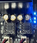
Some picture details ->
YELLOW capacitors:
224K/220nF/0,22µF - 1000V
pitch = 11,5mm
long. = 12,5mm
larg. = 5mm
high = 12mm
**************************
GRAY capacitors:
684K/680nF/0,68µF - 275V
pitch = 15mm
long. = 16,5mm
larg. = 10mm
high = 19mm
Possible 'upgrade' for PVDD capacitors ->
UPGRADED ORIGINAL
Rubycon ZLJ (Low Impedance Electrolytic Capacitors) * United Chemi-con KYB
2200µF/63V * 1200µF/63V
pitch = 7.5 mm * 7,5mm
diameter = 16mm * 16mm
Long. = 40mm * 31,5mm
Lifetime = 10000 Hours * 10000 Hours
ESR = 15MΩ * 20MΩ
Rej.cur. = 4,1A * 3A
Temp. = -40°C/+105°C * -40°C/+105°C
Tol. = 20% * 20%
N° Mouser= 232-63ZLJ2200M16X40 * 661-EKYB630E122MLN3S
Unit. price: 3,94 € * 2,79 €
I think LESTER will comment 😉
Have a good day.
Schematics ->
Some picture details ->
YELLOW capacitors:
224K/220nF/0,22µF - 1000V
pitch = 11,5mm
long. = 12,5mm
larg. = 5mm
high = 12mm
**************************
GRAY capacitors:
684K/680nF/0,68µF - 275V
pitch = 15mm
long. = 16,5mm
larg. = 10mm
high = 19mm
Possible 'upgrade' for PVDD capacitors ->
UPGRADED ORIGINAL
Rubycon ZLJ (Low Impedance Electrolytic Capacitors) * United Chemi-con KYB
2200µF/63V * 1200µF/63V
pitch = 7.5 mm * 7,5mm
diameter = 16mm * 16mm
Long. = 40mm * 31,5mm
Lifetime = 10000 Hours * 10000 Hours
ESR = 15MΩ * 20MΩ
Rej.cur. = 4,1A * 3A
Temp. = -40°C/+105°C * -40°C/+105°C
Tol. = 20% * 20%
N° Mouser= 232-63ZLJ2200M16X40 * 661-EKYB630E122MLN3S
Unit. price: 3,94 € * 2,79 €
I think LESTER will comment 😉
Have a good day.

The schematics reveals that you have to place a jumper per channel (solder dot) for bal or unbalanced input. Afterwards this is a fixed choice, to change bal/unbal input you have to change the jumper. Not very user friendly that is. There exist solutions that work with bal/unbal sources automagically without any alterations done by the user. But these require additional op-amps. From my point of view this is the result of bean counting at the wrong place.
hi bucks bunny: "What's up doctor ?" 🙂
-> That is a point of view, but I do not share it.
Indeed, I think it is easy for anyone to wire a small unique selector with wires (no relay) to switch between SE or BAL mode as is done on some high-end amplifiers ACCUPHASE, McINTOSH,...).
The purpose of this scheme is to reduce the number of components (with good quality), therefore the signal path, for a better SQ following the optimization of the input circuit which uses a double power rail for OPAMPS, which is almost never the case for 'competitive' PCBs.
This optimization has, among other things, made it possible to eliminate the duplicate capacitors on the path of the input signal, as is the case for the diagrams where the OPAMPS are powered by a single rail.
Here is an example to illustrate ->

You have to read the previous posts for a better understanding of my explanation.
Have a good day.
-> That is a point of view, but I do not share it.
Indeed, I think it is easy for anyone to wire a small unique selector with wires (no relay) to switch between SE or BAL mode as is done on some high-end amplifiers ACCUPHASE, McINTOSH,...).
The purpose of this scheme is to reduce the number of components (with good quality), therefore the signal path, for a better SQ following the optimization of the input circuit which uses a double power rail for OPAMPS, which is almost never the case for 'competitive' PCBs.
This optimization has, among other things, made it possible to eliminate the duplicate capacitors on the path of the input signal, as is the case for the diagrams where the OPAMPS are powered by a single rail.
Here is an example to illustrate ->
You have to read the previous posts for a better understanding of my explanation.
Have a good day.
Certainly we do not have the same point of view, i.e. share different opinions. Circuit design depends on personal priorities. I do not care much about the minimum number of parts in the signal path as long as other aspects dominate like best measured performance, highest EMV ruggedness and ease of use. I do not earn any money with my hobby projects and thus always look for the "best" solution - no bean counting here - but no boutique parts as well. So I prefer split supplies although in many cases I use virtual ground as well. What I do not like at all and consider a design flaw is a wire that connects a switch directy with the input of an op - as depicted in the schematics. Btw, did you check cell phone immunity of your designs?
just my 2c
just my 2c
Last edited:
We are not going to 'go around in circles' with our personal considerations: each reader will form their own opinion.
Your question (cell phone immunity) is addressed to the designer of the PCB: JLesterP.
In the meantime, I invite you to read the thread dedicated to the first version of this PCB (Sylph D200) on the ASR (Audio Science Review) site ->
https://www.audiosciencereview.com/...ics-sylph-d200-amplifier-module-review.25295/
Regards.
D
Deleted member 148505
TPA3255 EVM implements this jumper configuration as well, a frontend buffer is needed if you want to add a volume control or to automagically switch se/bal mode. It is not advisable to put wires directly on the opamp input, otherwise, it will act as an antenna. The module is immune to interference (light switch, cellphone text/call signals, etc.) provided that the wirings are correct.The schematics reveals that you have to place a jumper per channel (solder dot) for bal or unbalanced input. Afterwards this is a fixed choice, to change bal/unbal input you have to change the jumper. Not very user friendly that is. There exist solutions that work with bal/unbal sources automagically without any alterations done by the user. But these require additional op-amps. From my point of view this is the result of bean counting at the wrong place.
Also, this module is for a DIYer and not for an end user, so by being user friendly, you mean DIY friendly? The DIYer should be responsible on what features they are getting. This is not an 'all-in-one' module that only needs an aluminum case to be finished.
Regards,
Lester
I do not doubt that TI offers this jumper as well. But I feel free to do things different to TI whenever this looks preferrable to me. And in this case I prefer the more complex 4 op-amp input balancer circuitry - which at the end is more user friendly. Just one different opinion, nothing more, nothing less. R84 should be swapped with RJ4 to prevent direct wiring the op-input.
D
Deleted member 148505
Yes AgreedR84 should be swapped with RJ4 to prevent direct wiring the op-input.
Speaking of 'RJ4' I assume you are referring to 'SJ4' on the shematic.
I still have the impression that you have not fully grasped all the subtleties of this PCB...
... Don't blame me for that comment
Cordially.
I still have the impression that you have not fully grasped all the subtleties of this PCB...
... Don't blame me for that comment
Cordially.
D
Deleted member 148505
Bought a few hundreds of 10uF 63V Nichicon FG since the Elna Silmic II was not available anymore in Mouser and Digikey (EOL). We'll wait for the last buy option sometime this year.
Tried it and the datasheet sound description is correct. It has a good 'low end bass' (< 90Hz) and the highs are better than the green muse ES. Highs are somewhat more metallic (in a good way) which resembles what real cymbals sound like. Though I find the highs of the silmic ii better. PFFB smoothens out the highs of this FG cap. The vocals are generic sounding, there is no creaminess or magic when compared with the silmic ii. Overall impression, using this cap for input coupling is like pressing the loudness button on vintage amps, the bass and treble are more pronounced as compared with silmic ii which is flat sounding.
The silmic ii sounds more constrained in the lower mids, (400Hz) specially when opa1656 is being used. And there is 'veiled' or creamy or 'upper bassy' sound into it, more noticeable when you switch to other amps immediately. Silmic II is an acquired taste that you'll enjoy once you get used to it. Too bad that it's already discontinued. (Nichicon FG is EOL as well)
Attachments
Hello JLesterP 🙂
You still haven't tried the OPA828 ?
For my part, I'm waiting to have all my orders to mount my amp and would do the test with my OPA1656 as well 😉
I don't think there are any better 'alternatives' for FET OPAMPS as of now...
You still haven't tried the OPA828 ?
For my part, I'm waiting to have all my orders to mount my amp and would do the test with my OPA1656 as well 😉
I don't think there are any better 'alternatives' for FET OPAMPS as of now...
You found a typo!Speaking of 'RJ4' I assume you are referring to 'SJ4' on the shematic.
I still have the impression that you have not fully grasped all the subtleties of this PCB...
... Don't blame me for that comment
Cordially.
D
Deleted member 148505
Haven't tried OPA828 yet. What SMPS did you order for the Sylph-D200?You still haven't tried the OPA828 ?
You should 😉
For the SMPS, i still hesitate with some models...
Would you recommend one and in what voltage/power ?
For the SMPS, i still hesitate with some models...
Would you recommend one and in what voltage/power ?
Some remarks on plopping sound during power-up. At the moment the reset is released, the input biasing circuitry builds up and needs some time to stabilise while charging the coupling caps. There is an internal setup stabilisation muting to prevent from plop noise, but this is limited and a strong reason not to use bigger coupling caps than recommended by the data sheet. By experiments I discovered that reducing coupling capacity to 1uF and selecting paired capacitors reduced pops to nihil: The coupling capacitance unbalance is the elephant in the room. It is evident that electrolytic caps with their big tolerance are a source of unpredictable, individual pop sound levels. You better take some film caps with 5% tol or better. I use 1% selected pairs.
What 'Fc @ -3dB' do you get with 1µF capacitors (film or not) ?...
NB:
JLesterP didn't make a 'quick done' PCB as you seem to want to present it.
Can you show us your achievement with measurements validated by a third party like Amir from the Audio Science Review forum ?
Your photos would be welcome !
I know that JLesterP is a humble person and would surely be delighted to be able to take inspiration from your advice 🙄
Reminder ->
D
Deleted member 148505
Our TPA325X doesn't suffer on turn-on and off pop. However there is a random small 'turn-off' pop when PFFB is enabled. It is not really on turn-off scenario but it happens when the circuit is muted (using !reset pin on TPA325X IC, the voltage supervisor on our boards pulls the !reset pin on startup and shutdown to avoid large turn-on/off pops), according to ti e2e support, the input coupling caps discharges to the output via PFFB network when reset pin is pulled low. I've added a speaker shorting circuit on the latest Sylph-D400, but only reduced the pop to a very faint 'tick'.Some remarks on plopping sound during power-up. At the moment the reset is released, the input biasing circuitry builds up and needs some time to stabilise while charging the coupling caps. There is an internal setup stabilisation muting to prevent from plop noise, but this is limited and a strong reason not to use bigger coupling caps than recommended by the data sheet. By experiments I discovered that reducing coupling capacity to 1uF and selecting paired capacitors reduced pops to nihil: The coupling capacitance unbalance is the elephant in the room. It is evident that electrolytic caps with their big tolerance are a source of unpredictable, individual pop sound levels. You better take some film caps with 5% tol or better. I use 1% selected pairs.
Using 1uF will affect the low frequency response since the input impedance of TPA3255 is only 20k ohms.
Last edited by a moderator:
Thank you Lester for this precision on the BF answer, it seems that our friend 'thought' too quickly... 🙄
D
Deleted member 148505
The amp reviewed by Amir uses 4.7uF WIMA input coupling caps, optimal low freq response using 4.7uF cap is 16.93Hz.What 'Fc @ -3dB' do you get with 1µF capacitors (film or not) ?...
You can use caps maybe down until 3.3uF only.
- Home
- Amplifiers
- Class D
- JLE TPA3255 Build and Modifications