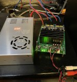
DAC and Amp installed in the living room.
Sound very. Smoothier than than old one 😀.
But problem with the level. Not enough loud, even with DAC at full.
In fact, i thought that a had a big margin because ARmin of Audiosciencereview wrote that the output level is 5.4Vrms. But it is NOT. It is half. I mesured 7.16V pp with my oscilloscope, means it is 2.53Vrms.
Sensivity of TPA is 2.7V rms, isn't it ?
I am thinking to boost the gain of the OPA1637 but i am worried of max level of TPA.
TVS or double zener on the output signal seems not be a good idea. What do you think ? Futhermore they ara often capacitive.
Second option, to limit the power voltage of OPA1637.
For positive, i can put a zener in parallel with CA4 but RA7 will burn (12-3.5)²/22
For negative, it is easy with my TPS7A30.
Third option, to supply the OPA1637 with TPS7A30 in GND/-7v. It should be the best option but will it add DC voltage mid supply on inputs ?
Any idea much appreciated ...
D
Deleted member 148505
DAC and Amp installed in the living room.
Sound very. Smoothier than than old one 😀.
But problem with the level. Not enough loud, even with DAC at full.
In fact, i thought that a had a big margin because ARmin of Audiosciencereview wrote that the output level is 5.4Vrms. But it is NOT. It is half. I mesured 7.16V pp with my oscilloscope, means it is 2.53Vrms.
Sensivity of TPA is 2.7V rms, isn't it ?
I am thinking to boost the gain of the OPA1637 but i am worried of max level of TPA.
TVS or double zener on the output signal seems not be a good idea. What do you think ? Futhermore they ara often capacitive.
Second option, to limit the power voltage of OPA1637.
For positive, i can put a zener in parallel with CA4 but RA7 will burn (12-3.5)²/22
For negative, it is easy with my TPS7A30.
Third option, to supply the OPA1637 with TPS7A30 in GND/-7v. It should be the best option but will it add DC voltage mid supply on inputs ?
Any idea much appreciated ...
Hi, can you measure the input/output voltage ratio of the module? 2.53Vrms measured from hot to cold signal?
Also you need to remove RA7/RA8 since you are using it to get the power for your daughter board.
What I did in my latest iteration is that I used LM317 to regulate positive rail down to 6.6VDC, then the output of switching negative generator is -6.6VDC.
Finally, TPS7A30/49 to get +/-6VDC rails.
D
Deleted member 148505
Speaking of RA7/RA8, I shorted it out and the sound impact is huge.
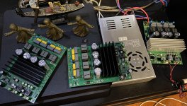
I have 3 modules here with different config (one is the orig non-pffb V1.1) to switch back and forth quickly so that I can compare the sound and select for the best.
I have 3 modules here with different config (one is the orig non-pffb V1.1) to switch back and forth quickly so that I can compare the sound and select for the best.
Attachments

D
Deleted member 148505
Are you doing blind tests? Please don’t put too much weight on sighted tests
Blind test is harder and time consuming, I'll let my biases decide for now. 😉
D
Deleted member 148505
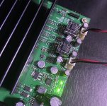
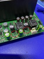
Aside from input cap selection, I think these 2 changes are enough to get noticeable improvement in sound quality (for TICore260BTL V1, V1A, V1B).
1. Remove opamp feedback caps. (1st pic)
2. Short out opamp supply resistor. (2nd pic)
1. Remove opamp feedback caps. (1st pic)
2. Short out opamp supply resistor. (2nd pic)
Attachments
Great work you did Daniboun. I did some tests last week with a 3eaudio module. I was very positively surprises about the soundstage and details on this ampboard. It was running next to a Pass ACA, a Sjostrom PA03 and a Pass M2X. I couldn't believe that let's say a 130 euro setup can compete with these amps but it did in my setup. I was running the 3eaudio module with a cheap 24v 10a smps, non LLC.Hi Jlester,
Thanks for the feedback.
For the switch I answered you by MP : no worries.
You made a nice module, I really like it. Yesterday we did a listening session with a friend of mine, he was impressed by the precision and dynamics of this module whether at low volume or at high volume.
You might give a test with some OP Amps Muse 02, it is really worth the while.
Last week I ordered the drMordor module and will buy the JLE module once they are available again. For me, all the fancy details and graphics are not that important. I listen with my ears not by looking at numbers.
Last edited:
The gain of my daughter board is correct =1 ...Hi, can you measure the input/output voltage ratio of the module? 2.53Vrms measured from hot to cold signal?
Also you need to remove RA7/RA8 since you are using it to get the power for your daughter board.
What I did in my latest iteration is that I used LM317 to regulate positive rail down to 6.6VDC, then the output of switching negative generator is -6.6VDC.
Finally, TPS7A30/49 to get +/-6VDC rails.
D
Deleted member 148505
You can use L7806 (to-92 package) It can be easily retrofitted on RA7. Use heatsink plaster to secure it in place after soldering.
As for opamp with different + and - voltage rails, there will be no side effect, as long as the output of the opamp is lower than the smaller rail voltage. OPA1637 will tolerate it without any problem. 🙂
As for opamp with different + and - voltage rails, there will be no side effect, as long as the output of the opamp is lower than the smaller rail voltage. OPA1637 will tolerate it without any problem. 🙂
Last edited by a moderator:
Good idea but i do not find to92 at digikey or mouser. Furthermore it cost 10€ each order ... 
And this is the third PCB i build ...
Building simulation, i think te only thing to respect is no more than 7v on input then i think i will try with a gain of 2 on OPA1637. 1k on input and 2k on output. 1K on input acts as a small voltage divisor with output impedance of dac, then the overall is a bit less of 2.
Result is, with 7.16vpp of DAC, 12vpp differential ot input of TPA (input_A-input_B) but no more than 3vpp. It shal clip but no destroy chip.
PS : totally agree with "As for opamp with different + and - voltage rails, there will be no side effect, as long as the output of the opamp is lower than the smaller rail voltage. OPA1637 will tolerate it without any problem."
D
Deleted member 148505
My bad, it's 78L06 not L7806, mouser and digikey here also has minimum order 50usd to avail for free shipping
Done.
Gain of about 1.68 with 1k In and 2k feedback (because of 374 ohm Zout of the DAC).
It is much better. With some music, it begin to clip (sound distortion and red led flashing) when volume close to max.
I confirm that the sound is much better without the small caps in parallel with the feedback resistor (around my opa1637).
Lester, do you think i should have much power if i adjust up a bit the rail of my SMPS, 48 to 50v for example ?
D
Deleted member 148505
Done.
Gain of about 1.68 with 1k In and 2k feedback (because of 374 ohm Zout of the DAC).
It is much better. With some music, it begin to clip (sound distortion and red led flashing) when volume close to max.
I confirm that the sound is much better without the small caps in parallel with the feedback resistor (around my opa1637).
Lester, do you think i should have much power if i adjust up a bit the rail of my SMPS, 48 to 50v for example ?
For 48VDC rails, onset of clipping is around (48V-8V) * 0.707 = 28.3Vrms, or 100W at 8 ohms. Increasing 48V to 50V rails, you'll just gain around 10W. Both 100W and 110W will have the same 'perceived' loudness.
Also check if the power supply output parts like capacitors are rated at 63V, if not, it's better not to increase the supply voltage.
Output impedance of your DAC is high, why not use 10:1 rule of thumb for impedance matching? Like 3.6K In and 6.2K feedback for OPA1637?
Regards,
Lester
Done.
Gain of about 1.68 with 1k In and 2k feedback (because of 374 ohm Zout of the DAC).
It is much better. With some music, it begin to clip (sound distortion and red led flashing) when volume close to max.
I confirm that the sound is much better without the small caps in parallel with the feedback resistor (around my opa1637).
Lester, do you think i should have much power if i adjust up a bit the rail of my SMPS, 48 to 50v for example ?
Question for you, since the OPA1637 is a fully differential OP amps : can we use it with any TPA3255 module with a DIP8 > SOIC8 adapter ?
Hi, can you measure the input/output voltage ratio of the module? 2.53Vrms measured from hot to cold signal?
Also you need to remove RA7/RA8 since you are using it to get the power for your daughter board.
What I did in my latest iteration is that I used LM317 to regulate positive rail down to 6.6VDC, then the output of switching negative generator is -6.6VDC.
Finally, TPS7A30/49 to get +/-6VDC rails.
Lester, i think the rails to protect TPA3255 should be +/-3.5v (not +/-6v). Effectively, this implies 3.5-(-3.5)=7v differential input_A - input_B.
Last edited:
I do not think so, the 1637 pinout is quite different from standard double opamp.Question for you, since the OPA1637 is a fully differential OP amps : can we use it with any TPA3255 module with a DIP8 > SOIC8 adapter ?
Furthermore, as Lester opinion, i think that one of the main gola is to suppres input caps. For that, it is needed to implement a negative voltage. Not so complex but you need a specific daughter board and that is what i done.
I do not think so, the 1637 pinout is quite different from standard double opamp.
Furthermore, as Lester opinion, i think that one of the main gola is to suppres input caps. For that, it is needed to implement a negative voltage. Not so complex but you need a specific daughter board and that is what i done.
Hummm sounds good... But If I am not wrong those OPA1637 have a Bi Polar input. Any chance to mount it with a traditionnal SOIC8 adapter without any risk ?

Lester, agreed with "perceived loudness". Sound level is a quite log curve.For 48VDC rails, onset of clipping is around (48V-8V) * 0.707 = 28.3Vrms, or 100W at 8 ohms. Increasing 48V to 50V rails, you'll just gain around 10W. Both 100W and 110W will have the same 'perceived' loudness.
Also check if the power supply output parts like capacitors are rated at 63V, if not, it's better not to increase the supply voltage.
Output impedance of your DAC is high, why not use 10:1 rule of thumb for impedance matching? Like 3.6K In and 6.2K feedback for OPA1637?
Regards,
Lester
Nevertheless, i will try to up at maximum rail (TPA should accept 53.5v).
About my voltage divisor ...

I do what i can ! I have a lot a component but never what i need 😡.
I put 1k on input because there are 0.01%. In general manner, i try to put the minimal resistance to low the contributed noise (according to current noise of the opamp mentionned in datasheet).
I know that my DAC is design with opa1612 and they are specified for good THD+N under 2k (not good at 600 ohms for example).
D
Deleted member 148505
Lester, i think the rails to protect TPA3255 should be +/-3.5v (not +/-6v). Effectively, this implies 3.5-(-3.5)=7v differential input_A - input_B.
Datasheet info is really incomplete. If you change the VBG reference voltage, the AVDD will become 10.5VDC (without fault). But AVDD max is 8.5VDC so not sure why they are allowing it.
The EVM designer also used 12Vpp for the opamp buffer so I think it's ok to use 12Vpp rails.
If you will use +/-3.5VDC, you need to find rail to rail opamp or you will have limited usable output.
D
Deleted member 148505
Lester, agreed with "perceived loudness". Sound level is a quite log curve.
Nevertheless, i will try to up at maximum rail (TPA should accept 53.5v).
About my voltage divisor ...
I do what i can ! I have a lot a component but never what i need 😡.
I put 1k on input because there are 0.01%. In general manner, i try to put the minimal resistance to low the contributed noise (according to current noise of the opamp mentionned in datasheet).
I know that my DAC is design with opa1612 and they are specified for good THD+N under 2k (not good at 600 ohms for example).
Make sure the SMPS can handle 53.5V.
Also based on datasheet "hints", 51V is max for 4 ohms load for BTL. They've only used 53.5V on 4 ohms load in SE and PBTL.
Last edited by a moderator:
- Home
- Amplifiers
- Class D
- JLE TPA3255 Build and Modifications