D
Deleted member 148505
For V1A and V1B, shorting out R8 and R10 further improves the sound. (R8 and R10 is series resistor similar to datasheet, on EVM it is 0R)
Even supplying GVDD has an impact in overall sound, that's why in my latest iteration, I've placed 10uF tantalum caps close to GVDD_AB CD supplies.
Even supplying GVDD has an impact in overall sound, that's why in my latest iteration, I've placed 10uF tantalum caps close to GVDD_AB CD supplies.
Oh, no 🙁 I have had a very poor experience with tantalum caps.
Well, one failed on me before, but it's the only kind of cap that failed me (and was difficult to diagnose), so...
FWIW Rod Elliott hates them too
Well, one failed on me before, but it's the only kind of cap that failed me (and was difficult to diagnose), so...
FWIW Rod Elliott hates them too
Last edited:
D
Deleted member 148505
Really depends on circuit application, they have their own place if you know where to apply them.
D
Deleted member 148505
Bi polar or CMOS or JFET does not change anything.Hummm sounds good... But If I am not wrong those OPA1637 have a Bi Polar input. Any chance to mount it with a traditionnal SOIC8 adapter without any risk ?
You should have to check the pinout datasheet because i cannot see enough the wiring of your adapter.
Not sure to understand 🙁. What is VBG ? the middle voltage for biaising input ?Datasheet info is really incomplete. If you change the VBG reference voltage, the AVDD will become 10.5VDC (without fault). But AVDD max is 8.5VDC so not sure why they are allowing it.
The EVM designer also used 12Vpp for the opamp buffer so I think it's ok to use 12Vpp rails.
If you will use +/-3.5VDC, you need to find rail to rail opamp or you will have limited usable output.
Following to that, up the 12v to 13v would it improve the ability to accept more input voltage, and then the gain ?
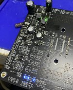
Yeah, good teasing.Latest update 🙂
Good choice for the blue leds, it improves the sound also

D
Deleted member 148505
Yeah, good teasing.
Good choice for the blue leds, it improves the sound also
Haha, even their brightness are fine tuned, all of the LEDs (and the green LED at the top) now have the same brightness, lol.

Does the reliability change depending on the application?Really depends on circuit application, they have their own place if you know where to apply them.
D
Deleted member 148505
Does the reliability change depending on the application?
Yes it's more reliable than electrolytic provided that you will use it on low voltage and low voltage surge, no reverse voltage spikes, and low ripple current applications.
Last edited by a moderator:
HelloFor V1A and V1B, shorting out R8 and R10 further improves the sound. (R8 and R10 is series resistor similar to datasheet, on EVM it is 0R)
and for V1? R?
Regards
Roger
D
Deleted member 148505
Hello
and for V1? R?
Regards
Roger
Does not exist in V1, which is good as it is not needed.
Latest update 🙂
Where are the op-amps Lester? Mounted underneath? I’m presuming 1656s? Are you the guy who wiped out the supply in the US? 😉
Pete
What 😱😱😱 ?
Lester did not implement real diff driver?
My bad..you are correct....😕
I thought he was just trying to get rid of input electrolytics on this next version

D
Deleted member 148505
Haha someone hyped up the OPA1656, that's why the demand surged.Where are the op-amps Lester? Mounted underneath? I’m presuming 1656s? Are you the guy who wiped out the supply in the US? 😉
Pete
Should I put SOIC-8 under the DIP-8 socket (like 3eaudio)? I think it will have a better connection if it's soldered directly. (After opamp rolling has been made)
Yes only dual opamps for now.What 😱😱😱 ?
Lester did not implement real diff driver
My bad..you are correct....😕
I thought he was just trying to get rid of input electrolytics on this next version
Yes the goal is to have a split supply to remove the input electrolytics. Most available space was eaten by the regulators.
Personally, I don't care one bit about opamp rolling. For me:
1) Input headers with gold-plated posts (shame on you TI)
2) Electrolytics are OK as long as they are used smartly (bipolar or back-to-back, and extra uF to avoid any effect on audio band)
3) Very low noise
4) Lowest-possible IMD and HD3+
5) Adjustable gain with THT resistors would be nice
1) Input headers with gold-plated posts (shame on you TI)
2) Electrolytics are OK as long as they are used smartly (bipolar or back-to-back, and extra uF to avoid any effect on audio band)
3) Very low noise
4) Lowest-possible IMD and HD3+
5) Adjustable gain with THT resistors would be nice
Last edited:
- Home
- Amplifiers
- Class D
- JLE TPA3255 Build and Modifications