Then why use it at all? X7R or polymer no good?Yes it's more reliable than electrolytic provided that you will use it on low voltage and low voltage surge, no reverse voltage spikes, and low ripple current applications.
D
Deleted member 148505
Then why use it at all? X7R or polymer no good?
Sometimes the ESR or tantalum cap helps with suppressing voltage transients.
https://www.analog.com/media/en/technical-documentation/application-notes/an88f.pdf
Then ceramic caps reduce their value when you apply DC bias on them. Also decreases with temperature vs tantalum caps. Tantalum increases their capacitance with temp.
Does the capacitance change when a DC voltage is applied to ceramic capacitors? Are there any points to be aware of regarding changes in the capacitance? | Murata Manufacturing Co., Ltd.
So you can't blindly replace electro and tanta with X7R. Some voltage regulators require putting a series low value resistor to 10uF X7R for stability if a tantalum cap is not available.
Though I will use electrolytic cap under the board next time for Gvdd_CD because tantalum cap is expensive (cost optimization).
The cost of manufacturing SMT + board doubled because I used 10uF X7R and tantalum all over + the cost of TPS7A49/30 and additional regulators.
Ah, right. Well, may still be an option to use higher-voltage-rating ceramic caps in order to maintain a higher actual capacitance (I think tomchr recommends 100V X7Rs for decoupling).
D
Deleted member 148505
Yes same with tantalum, if placed on hot part of the PCB, requires 50% voltage derating. So I'll just use 105 deg electrolytic next time to reduce the cost 🙂
In the 1970s Delco (GM) started putting Tantalum caps in their radios. It was a big mistake, since an automobile has too many over voltage spikes on the +12V supply. Delco replaced a lot of Tantalum caps in radios under warranty. Those Tantalum caps are very unforgiving for over voltage and reverse voltage spikes. Tantalum caps work well, if not abused, though.
Bad mood today ...
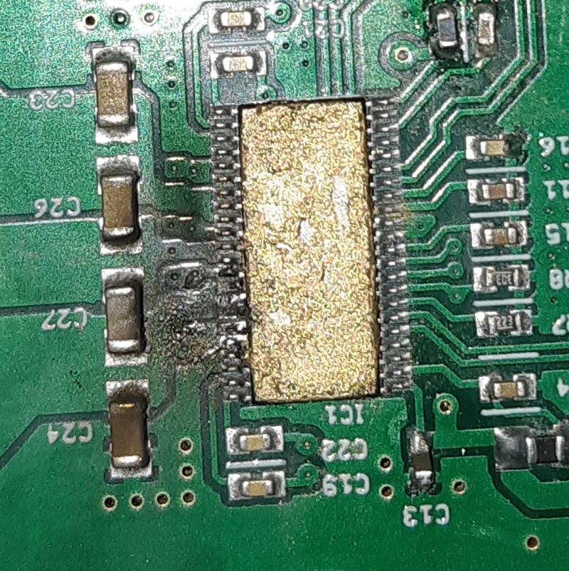
first pb this morning when adding 4.7uF in parallel with 100nF for GVDDs. When supplying, issue because interference between the caps and the dissipator.
I desoldered.
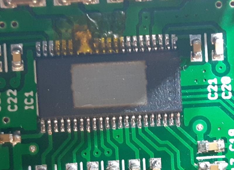
I cleaned the TPA chip. I changed the cooling paste on top of it (not the same as usual).
I supplied and ... ploufff. May be a shortcut with the new cooling paste ...
PCB is a bit destroy on the three PVDD_AB pins.
I should try the replaced it, isn't it ?
first pb this morning when adding 4.7uF in parallel with 100nF for GVDDs. When supplying, issue because interference between the caps and the dissipator.
I desoldered.
I cleaned the TPA chip. I changed the cooling paste on top of it (not the same as usual).
I supplied and ... ploufff. May be a shortcut with the new cooling paste ...
PCB is a bit destroy on the three PVDD_AB pins.
I should try the replaced it, isn't it ?
Last edited:
D
Deleted member 148505
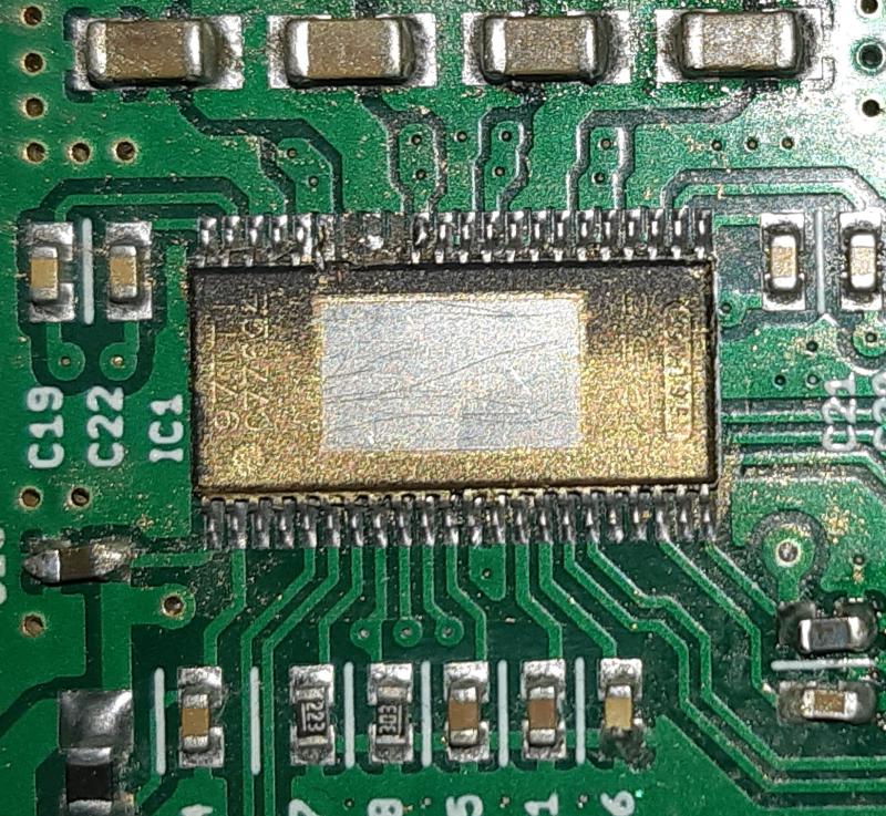
What's the cooling paste that you've used? Looks like real gold and conductive.
Chipquik with chisel type iron tip is good to remove the IC. Safer than using hot air.
After removing the IC, inspect if there are other bad traces.
If the other traces are still good, then you can still use the PCB by scratching the PVDD trace and by putting wire jumper to the IC. Then apply some heatsink plaster/glue on top to make the wiring stable.
 )
)
Oh, boy.
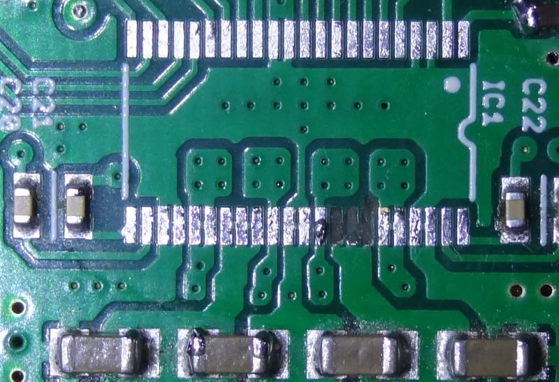
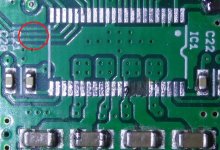
I just had a thought - what if you extended the traces just a little bit past the pad on the inside? Right now there's not much stopping the delamination, but if you had trace on both sides of the pad, the pad would be pretty well anchored down...?
Or is it just a coincidence that only the dead-end pads lifted off?
D
Deleted member 148505
Still looks good I think, I've seen worse pcb pads being repaired in youtube.
Oh, boy.
I just had a thought - what if you extended the traces just a little bit past the pad on the inside? Right now there's not much stopping the delamination, but if you had trace on both sides of the pad, the pad would be pretty well anchored down...?
Or is it just a coincidence that only the dead-end pads lifted off?
Grounding is critical, every space counts. In my latest iteration, I've made these traces thinner to increase ground pour area.
Attachments
The best way to solder it is to pray.
A lot .
.
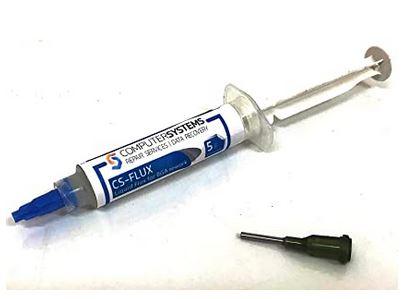
To be serious, my method is to put a lot a solder everywhere. After that, to absord it with that :
 .
.
Putting a bit of solder flux help defore absborbing :
Not so difficult to do that .
.
I am waiting my new 6 1/2 digits multimeter to sort resistors of the in the diff input and enjoy .
.
A lot
.To be serious, my method is to put a lot a solder everywhere. After that, to absord it with that :
.Putting a bit of solder flux help defore absborbing :
Not so difficult to do that
.I am waiting my new 6 1/2 digits multimeter to sort resistors of the in the diff input and enjoy
.Strange, i received new JLester comments noticed by email but nothing seeing on the website ...
Hello
Same for JL's post
You are going to sort resistances of what precision?
The minimum goal of distortion for this differential stage
Regards
Roger
Same for JL's post
You are going to sort resistances of what precision?
The minimum goal of distortion for this differential stage
Regards
Roger
D
Deleted member 148505
I deleted the post haha.
My method for soldering TPA3255 is different.
I'm using 0.8mm soldering lead.
Then I solder the two pin on each corner of the chip, put lots of flux all around then solder drag from 2 pin to the rest of the pins. Then apply the iron on each pin back and forth.
If there is remaining solder blob, I clean the iron tip and put it on the blob to adsorb it.
Last edited by a moderator:
D
Deleted member 148505
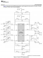
With Kenny G's "Songbird" I was able to identify the constrained sound of PFFB. (In my speaker)
The constrained sound is there because of the removal or attenuation of the 'low-end' midrange. Higher midrange is more boosted. For example, in Songbird, the saxophone's low end sound is attenuated which is not pleasant to the ears.
For TICore260BTL users with 36VDC rails, you can replace RG1 to RG4 with 2K ohm 0603 low ppm resistor (matched resistor with up to 1 ohm difference is better).
Since it will result to lower negative feedback, the THD will also go higher, but the midrange sound will be as good as non-PFFB sound. 🙂
For 48V DC rails it is also working in room casual listening, but I will test first for stability in high power output.

D
Deleted member 148505
I don't have your schematic, but in the feedback T-filter, are your RG1-RG4 resistors in the same location as the TI EVM R_fb-gnd resistors to ground?
Yes, correct. But with further listening, I still detect small constrained sound + the highs are inferior to slaa788a PFFB.
I already found another solution, (I can't detect the constrained sound anymore + Bass is better) it will be available to TICore260BTL V1 to V1B users soon. (depending on the test result)
Last edited by a moderator:
- Home
- Amplifiers
- Class D
- JLE TPA3255 Build and Modifications