You mean something like this ?
Yep, now lower R15/18 to give the BD's a bit more current (say 22 ohm to start with? (resulting in 600mV/22 = 27.2727272727273mA+-)).
Can not get that low.... below 60ohm things seem to be unstable.... at 35 ohm spice does not even work 🙂
Will try to get a good balance
Will try to get a good balance
well, to use drivers collector resistors as 22ohm, I also used 22ohm for the same drivers emitters.
It seems almost good, but I do not have exactly the same currents in the positive and negative output collectors..... That might cause distortion due to the different gains of the upper and lower output transistors
It seems almost good, but I do not have exactly the same currents in the positive and negative output collectors..... That might cause distortion due to the different gains of the upper and lower output transistors
Attachments
I will try to null offset and see if both currents get the same values.
Now I am worrying about stability.... Most CFP output stages I have seen (appart from the original Nobrainer that I have built) use a compensation cap in the negative side driver.
I do not really know why this should be but should I use one of those caps ?
Now I am worrying about stability.... Most CFP output stages I have seen (appart from the original Nobrainer that I have built) use a compensation cap in the negative side driver.
I do not really know why this should be but should I use one of those caps ?
Now I am worrying about stability.... Most CFP output stages I have seen (appart from the original Nobrainer that I have built) use a compensation cap in the negative side driver.
I do not really know why this should be but should I use one of those caps ?
Don't, but do the impedances sufficient low, use base stoppers when needed and after that (when things are not stable) we will see what measures are needed.
well, to use drivers collector resistors as 22ohm, I also used 22ohm for the same drivers emitters.
It seems almost good, but I do not have exactly the same currents in the positive and negative output collectors..... That might cause distortion due to the different gains of the upper and lower output transistors
Care about the offset, the unequal current will then be taken care of 🙂 (if you can see the logic of this).
Don't, but do the impedances sufficient low, use base stoppers when needed and after that (when things are not stable) we will see what measures are needed.
What impedances are you referring to ?
What impedances are you referring to ?
We where talking (I think) about the CFP's and surrounding circuitry 🙂
Ok, I can null output offset and that makes currents in the output transistors collector dummy resistors almost the same but current in the emitters (positive to negative side) are not the same because current in BD139 is 24.6mA and current in BD140 is 33.3mA.
Maybe this is due to the differences in these transistors spice models..... Anyway the same "issue" exists in the original Nobrainer simulation and it works perfectly.... So we are good to go.
I am inclined to start collecting parts for this build and would appreciate your opinion about the output transistors.... should I stick to D44 / D45H11 ?
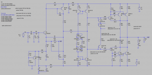
Stability sweep
Finally have time to study this amp again.
I have been looking at the stability and it looks I can use a miller cap as low as 10p as long as I settle with a value of C2 also equal to 10p.
Strangely, if I use a large C2 (30p for example), the amp looks stable even with a very small 6p for miller cap.
Am I doing something wrong or is this amp exceptionally stable ?
Attachments
The lag capacitor C2 reduces the bandwith too so it could well be that a small Miller is OK.
Your two transitor gain system has it´s own Miller capacitance anyway.
If you would casccode them you may need a bigger Miller cap.
Your two transitor gain system has it´s own Miller capacitance anyway.
If you would casccode them you may need a bigger Miller cap.
I am looking forward to this.
Stabilty is often an advantage of simple circuits.
When distortion does not get too high it could sound very well.
Not that i care much about distortion less then 0.1% low order.
Stabilty is often an advantage of simple circuits.
When distortion does not get too high it could sound very well.
Not that i care much about distortion less then 0.1% low order.
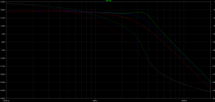
THD is a little under 0.1%, thats what i said.
Anyway, the prove is in the listening. It is more important that distortion is consistent with frequency and power.
In the new Audio magazine in Germany a singled ended tube amp got 140 points ( record ) and has much more distortion then this. Although mainly second and very monotonic.
Anyway, the prove is in the listening. It is more important that distortion is consistent with frequency and power.
In the new Audio magazine in Germany a singled ended tube amp got 140 points ( record ) and has much more distortion then this. Although mainly second and very monotonic.
Yesterday I had a big issue with my original Nobrainer.
I have been arranging my stuff after moving to another apartment where I have one room dedicated to DIY. 🙂
Finnaly unpacked the TT, the riaa amp, preamp and Nobrainer and connected everything to an old pair of Yamaha 690 monitors.
While accessing sound quality, I found a difference in level between channels, so I decided to switch cartridge cables just to determine the cause.
When I removed one cable, I heard a loud snap in the corresponding speaker and fumes starting whoozing out of the Nobrainer.
Opened it up and the output negative transistor was blown.
I do not know what happened but I guess the transient caused by disconnecting the cart cable was enough to cause instant damage on the output stage.
Today I replaced the drivers and the output trannies and everything came back to normal.
Can not figure out what happened but would like to implement some kind of security to avoid possible misfortunes.
You can clamp the input voltage to say 4V. Frans has shown me a circuit with a mosfet and a zener that conducts a near short over 4V.
You can use anti parallel zeners for the time being at the input.
You can use anti parallel zeners for the time being at the input.
- Status
- Not open for further replies.
- Home
- Source & Line
- Analogue Source
- JG´s Nobrainer and Nobrainer Discrete