
You are great guys from Ukraine 🙂
So there you are!!
the circuit is good for 100W RMS
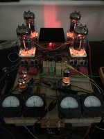
It is the circuit I have already soldered but not put in the case....
Hello, can you share the project files? What changes are e looking at for 50w version? This looks like a good project for me!
What transistors are you planning in the output stage? Will you make the boards yourself or order in China? There are two options for circuit.Hello, can you share the project files? What changes are e looking at for 50w version? This looks like a good project for me!
I can customize PCB in Altium. I can use PCBway for fabrication. I see you already have share and sell there but is it accurate? Also, can SMPS be used instead of linear supplies? Plan to use https://unitedsic.com/products/sic-jfets/uj3n065080k3s/
I tried it on a breadboard and it worked.Also, can SMPS be used instead of linear supplies?
myfirstamplifier,
I posted on PCBway a pcb for ordering. If this pcb suits you, you can order it there. Q1 - 2N5457, Q2 - J113
https://www.pcbway.com/project/shareproject/JFET_only_Circlotrons_without_negative_feedback__2.html
Last edited:
These JFETs are very difficult to work with. I wrote about it in messages #199, 200.I can get uj3n065080k3s next day via Mouser.
Last edited:
For UJ3N065080K3S it will be better to use this pcb:
https://www.pcbway.com/project/shareproject/JFET_only_Circlotrons_without_negative_feedback_v2.html
https://www.pcbway.com/project/shareproject/JFET_only_Circlotrons_without_negative_feedback_v2.html
Hi there,
Did you have any success with something more linear than uj3n065080k3s?
I designed and build my own circlotron with tubes a few years ago and I’m thinking to replace the 6c33c with a power JFET. Want to reach 100W in class A. I already have the cases with 4 huge heatsinks that can host some 16 transistors per side in parallel (with separate bias circuit for each).
Regards,
Silviu
Attachments
Congratulations!
The uj3n065080k3s is a very nice JFET. It has intermediate characteristics between a pentode and a triode. This can be seen from its data sheet.
Large heatsinks will be needed. Because it has thermal stability at high current.
It will be very good with SIT-JFET.
We used KP802A. But with them, the power is less than 100 W.
In general, a large power was not needed. Amplifiers without feedback are not afraid of clipping. It is imperceptible to them. It is possible to hold high average power without compromising quality.
Where can I look at your 6C33C amplifier?
Last edited:
@myfirstamplifierFor UJ3N065080K3S it will be better to use this pcb:
https://www.pcbway.com/project/shareproject/JFET_only_Circlotrons_without_negative_feedback_v2.html
UJ3 series is my favourite JFETs. Low Ciss, very nice curves, i like them most of all other FETs.
You should use the PCB suggested by our friends here. I have mine but is very expensive 6-layer and the design is really difficult to tune, so you should better use the one suggested.
You can try various JFETs in input stage, as long as they follow the rules described in the schematic regarding Idss. Just make sure they are original.
For UJ3 you must ensure that you get about -9V in their gate. Adjust the SMPS input and/or registors of the design to get this voltage.
For sure you can use SMPS and I would recommend them at first and maybe very later you can change to a linear one.
P.S. You need some kind of delay of main start, because you don't want to give to FETs the full voltage before their gates reach -9V, because it practically means short circuit.
Last edited:
Nice project SavuHi there,
Did you have any success with something more linear than uj3n065080k3s?
I designed and build my own circlotron with tubes a few years ago and I’m thinking to replace the 6c33c with a power JFET. Want to reach 100W in class A. I already have the cases with 4 huge heatsinks that can host some 16 transistors per side in parallel (with separate bias circuit for each).
Regards,
Silviu
Now, to reach 100W class A (on 8 ohm I guess).
- You need to be able to dissipate a lot of heat. I haven't tried that much in this amplifier (although I have in other designs), but in simulation it seems you need to dissipate more than 400W. Now that's a lot of heat for any kind of heatsink.
- You need to swing 45Vpp in input of FETs, that was not an easy task with this design.
My suggestion would be to go with 1A bias and aim for 60-80W output (not class A). Then you would need to dissipate 70W and since you are on tubes, you must already have some sensitive speakers, so it would work great. In such a setup any speaker above 89db would be fine, unless you have a really big room.
Then you can always change the bias point and slowly dissipate more heat to increase the Class A area.
If only I could find UJ3 with a lower voltage Vds. We do not need such a margin of 650 V, but such UJ3 probably does not exist.UJ3 series is my favourite JFETs.
@jpatay How much Volts would we need? About 200V? We could ask them 🙂 . But what about setting up a set of requirements and ask them if they can produce and see what happens 🙂 . For example, I would like to have MT200 or TO-264-3 package because I want to dissipate more heat easily.
I was talking to them in the old days but since they are bought from Qorvo, they are not much responsive, but you never know
BTW did you see their new UJ4S series? Unfortunately 750V
I was talking to them in the old days but since they are bought from Qorvo, they are not much responsive, but you never know
BTW did you see their new UJ4S series? Unfortunately 750V
My amp was sent to my hometown for storage when I moved from Ireland to Switzernad. I think I still have the circuit.Congratulations!
The uj3n065080k3s is a very nice JFET. It has intermediate characteristics between a pentode and a triode. This can be seen from its data sheet.
Large heatsinks will be needed. Because it has thermal stability at high current.
It will be very good with SIT-JFET.
We used KP802A. But with them, the power is less than 100 W.
In general, a large power was not needed. Amplifiers without feedback are not afraid of clipping. It is imperceptible to them. It is possible to hold high average power without compromising quality.
Where can I look at your 6C33C amplifier?
It has a differential cascode with ecc88 a ccs in it’s tail with a pentode (can use a cascode also), 100k 0.01% wirewound as anode loads feeding mosfet source followers (from Bartola tubes). One source follower for each 6c33c in the circlotron output stage.
Supply for differential cascode is +300Vcc/-160Vcc, for source followers is +160Vcc/-160Vcc and for the circlotron output stage it’s 2x140Vcc
All supplies are regulated from 230/230 & 230/120 transformers, output stage supplies are SMPS. Each stage has it’s own separte supply.
Everything is fully balanced from input to output, feeding a ESL63 electrostatic speaker.
I have acquired two huge chassis made trough a special order here on diyaudio. The supplier is an Italian company.Nice project Savu
Now, to reach 100W class A (on 8 ohm I guess).
- You need to be able to dissipate a lot of heat. I haven't tried that much in this amplifier (although I have in other designs), but in simulation it seems you need to dissipate more than 400W. Now that's a lot of heat for any kind of heatsink.
- You need to swing 45Vpp in input of FETs, that was not an easy task with this design.
My suggestion would be to go with 1A bias and aim for 60-80W output (not class A). Then you would need to dissipate 70W and since you are on tubes, you must already have some sensitive speakers, so it would work great. In such a setup any speaker above 89db would be fine, unless you have a really big room.
Then you can always change the bias point and slowly dissipate more heat to increase the Class A area.
Hope I can find the link.
LE: the link: https://www.diyaudio.com/community/threads/picos-toxic-masculinity-class-a-amp-chassis.362494/
Last edited:
What about the GaN mosfets available on Mouser. Would those be an improvement? Brand is Transphorm@myfirstamplifier
UJ3 series is my favourite JFETs. Low Ciss, very nice curves, i like them most of all other FETs.
You should use the PCB suggested by our friends here. I have mine but is very expensive 6-layer and the design is really difficult to tune, so you should better use the one suggested.
You can try various JFETs in input stage, as long as they follow the rules described in the schematic regarding Idss. Just make sure they are original.
For UJ3 you must ensure that you get about -9V in their gate. Adjust the SMPS input and/or registors of the design to get this voltage.
For sure you can use SMPS and I would recommend them at first and maybe very later you can change to a linear one.
P.S. You need some kind of delay of main start, because you don't want to give to FETs the full voltage before their gates reach -9V, because it practically means short circuit.
@savu
That would be really interesting, I was looking also at them. I have run LTSpice circlotron simulation for them and got remarkable results!
The problem I had with them is that I had much difficult time to use their package in my platform and application. And also check their useful area, they are not meant for Big Class A currents, practically they are not meant to dissipate more that 40W each . But you mentioned you are going to use many of them in parallel, so you can go for it!
Regarding the heatsink, i would suggest that since circlotron design permits adjusting of Class A current, you just build it and reach the point your heatsinks can manage (in summer 🙂 )
And if your' re searching the tube like sound, you can always use 2SK182ES! That is my current setup but with these I found difficult to go over 60W. But they have best sound (at least for my ears)
- Home
- Amplifiers
- Solid State
- JFET-only Circlotrons without negative feedback