Allright, here we go the F-buttons didn´t communicate....
S1 = 1336.00e-4;
S2 = 1336.03e-4;
S3 = 1338.00e-4;
S4 = 4149.33e-4;
S5 = 6922.00e-4;
L12 = 0.80e-2;
L23 = 45.80e-2;
L34 = 23.00e-2;
L45 = 10.40e-2;
Vtc = 80000.00e-6;
Atc = 3000.00e-4;
Parameter Conversions:
Sd=1140.00cm2
Bl=15.49Tm
Cms=2.78E-04m/N
Rms=2.07Ns/m
fs=32.9991Hz |Mmd = 61.54g not recognised by AkAbak, fs calculated and used instead
Le=1.00mH
Re=5.20ohm
ExpoLe=1
best I could do at the moment
No problem tb! Where are Ap1 & Lpt discussed in detail regarding TH's? I do recall seeing a thread where there was a pic of a ported chamber TH in Hornresp.Hi,
BP1Fanatic: in the Hornresp Input Parameters (Post #193) you have Ap1 and Lpt as 0.00. This is obviously incorrect, even if Hornresp doesn't lock up on it; Hornresp should probably flag this and not just insert some nominal values that may or may not have anything to do with the model. The throat chamber, and the transition form the throat chamber into the horn propper, will affect the Hornresp impulse response quite severely, and should be modelled accurately.
I just read Hornresp Help. It states that if Ap1 = Atc, then no inputs are needed for Ap1 & Lpt.
Last edited:

measuring achievement
which sound measurement tools do you recommend?
I have
a simple dB meter, which can measure peak and continuous levels
an ultracurve pro with a matching ECM 8000 microphone - which i have yet to learn to use 😱
it seems pretty complex and apparently contains the equivalent of a whole old-school rack!
so far i have measured 1m from a cabinet, and played frequencies, one at a time, and as pink noise, simply to get a response curve and get to know the equipment.
has anyone written a handy guide like littlemike's, but for the DEQ2496?
Thanks!
Ben
PS. good news, got some free ply, a bit scrappy, but fine for a bbq after testing cabinets!
There are several measurement threads out there, penngray just started a good one on HolmImpulse over at AVS, and there are two in HI started by the program's author here, just search for them. REW is heavily discussed over at HTShack.
You have most of the right parts, just add a laptop and a decent sound card and install some free software. I use RoomEQWizard and HolmImpulse for SPL measurements, you can get impedance with ARTA or Praxis (free versions), or you can get a dedicated box like the WT2 from Smith & Larson or the WT3 from PE (big difference in accuracy and capability, the WT2 does a lot more for an additional $50).
Laptop? As long as it runs XP and has a USB port, you're set. Slow CPU = slow FFT processing, but so what. It will get the job done. I use a 5-year-old Dell.
As far as sound cards, it is hard to beat the capability of the Behringer UCA-202 for $30, period. It certainly is a PITA to set up, because windows does it all wrong and you have to fix that, but once set up, it is essentially flat from 5 Hz to 20 Khz out of the box, with a simple loopback calibration, you can get ruler flat baselines.
Post #203_BP1Fanatic_Impulse Response
Hi BP1Fanatic,
Just back from another fun weekend of remodeling (why do we do these things to ourselves?).
The short answer is no, but let's see:
From my limited understanding the impulse response is just another way of looking at the frequency response, and maybe that's too simple. I have not seen any measured impulse response graphs for a tapped horn done, and explained by, for example DSL. Most of my time spend comparing the transient responses for a given speaker in closed/sealed boxes, bass reflex enclosures, horns, tubes and tapped horns has only been on paper, and mainly in Hornresp. I spend a considerable amount of time listening to different loudspeaker designs in the 1970s, and developed a clear preference for sealed bass enclosures.
You may already be familiar with one of the better articles about the subject of measuring loudspeakers, if not I highly recommend it and its sidebar on the FFT: "Measuring Loudspeakers, by John Atkinson, stereophile.com/features/100/#". At least it seems more accessible to me than some of the more scholarly mathematical dissertations you can quickly find with the google. Also, John Atkinson points out the problems associated with any of these measurements and computations. He even delves briefly into "panel vibrational behavior" which may well be the answer to a large part of the fortuitous 3dB hole filling performance in screamerusa's furyboxes SPL response (that, and the throat/initial horn section treatment).
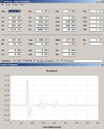
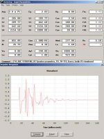
Once upon a time in the "collaborative TH thread" we tried to get an idea of how the TH-115 may be folded, and even though we never arrived at any particular solution I ended up with one that had what I would consider a reference impulse response for a tapped horn. When I add a small throat chamber to the design the frequency response is only slightly affected, but the impulse response looks really bad. Apparently the chamber resonances mess up the impulse response.
It would take much more time for me than I have available to form an educated opinion on the merrits-or cause-of this or that feature in the impulse response of a tapped horn, but maybe this example explains why I don't have any real opinion on the subject beyond considering something like the TH-115-Guess impulse response desirable.
Hope this helps,
Regards,
Hi BP1Fanatic,
Just back from another fun weekend of remodeling (why do we do these things to ourselves?).
The short answer is no, but let's see:
From my limited understanding the impulse response is just another way of looking at the frequency response, and maybe that's too simple. I have not seen any measured impulse response graphs for a tapped horn done, and explained by, for example DSL. Most of my time spend comparing the transient responses for a given speaker in closed/sealed boxes, bass reflex enclosures, horns, tubes and tapped horns has only been on paper, and mainly in Hornresp. I spend a considerable amount of time listening to different loudspeaker designs in the 1970s, and developed a clear preference for sealed bass enclosures.
You may already be familiar with one of the better articles about the subject of measuring loudspeakers, if not I highly recommend it and its sidebar on the FFT: "Measuring Loudspeakers, by John Atkinson, stereophile.com/features/100/#". At least it seems more accessible to me than some of the more scholarly mathematical dissertations you can quickly find with the google. Also, John Atkinson points out the problems associated with any of these measurements and computations. He even delves briefly into "panel vibrational behavior" which may well be the answer to a large part of the fortuitous 3dB hole filling performance in screamerusa's furyboxes SPL response (that, and the throat/initial horn section treatment).
Once upon a time in the "collaborative TH thread" we tried to get an idea of how the TH-115 may be folded, and even though we never arrived at any particular solution I ended up with one that had what I would consider a reference impulse response for a tapped horn. When I add a small throat chamber to the design the frequency response is only slightly affected, but the impulse response looks really bad. Apparently the chamber resonances mess up the impulse response.
It would take much more time for me than I have available to form an educated opinion on the merrits-or cause-of this or that feature in the impulse response of a tapped horn, but maybe this example explains why I don't have any real opinion on the subject beyond considering something like the TH-115-Guess impulse response desirable.
Hope this helps,
Regards,
Attachments
EXCELLENT explanation TB46! Unless you have the physical driver, you really can't calculate the volume inside the cone?Hi,
I have noted that there seem to be questions as to what is or isn't the throat chamber, and how to enter it into Hornresp. Maybe this example for a short L12 plus chambered driver helps:
Regards,
oliver:
update on my 24x24x48 box.
It was a little windy today, so I did 5.6, instead of 2.8v measurements. I did all kinds of baffle/no baffle trials, and still couldn't get rid of the NASTY 100hz null... I mean it falls off a cliff at 100.
I tried a shallow baffle at the bottom/back, and that really helped the 80-90hz....
Without a 45 degree baffle either top/front or top/back, I get a stuffy 70hz sound, and about 1.5db extra at 50hz. It's worth the trade off to lose a little 50hz to get a clean 70hz sound.
I don't really care that this sub falls off a cliff at 100 because of the way I plan on using it, but do you have any idea where I could try to change something to lessen it?
The following is with a shallow baffle at bottom/back, and a 45 degree top/back, no other bracing.
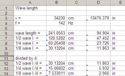
5.6v @1m
40 102.5
41 103
42 104.5
43 105.5
44 106
45 106
50 107.5
55 107.5
60 107.5
65 107
70 106
75 106.5
80 107
85 108.5
90 110
95 110
97 106
98 103
99 100
100 98
update on my 24x24x48 box.
It was a little windy today, so I did 5.6, instead of 2.8v measurements. I did all kinds of baffle/no baffle trials, and still couldn't get rid of the NASTY 100hz null... I mean it falls off a cliff at 100.
I tried a shallow baffle at the bottom/back, and that really helped the 80-90hz....
Without a 45 degree baffle either top/front or top/back, I get a stuffy 70hz sound, and about 1.5db extra at 50hz. It's worth the trade off to lose a little 50hz to get a clean 70hz sound.
I don't really care that this sub falls off a cliff at 100 because of the way I plan on using it, but do you have any idea where I could try to change something to lessen it?
The following is with a shallow baffle at bottom/back, and a 45 degree top/back, no other bracing.
5.6v @1m
40 102.5
41 103
42 104.5
43 105.5
44 106
45 106
50 107.5
55 107.5
60 107.5
65 107
70 106
75 106.5
80 107
85 108.5
90 110
95 110
97 106
98 103
99 100
100 98
Attachments
Last edited:
jbell_24x24x48
Hi jbell,
Thanks for the additional information. Those are really very impressive measurements. Even without knowing the exact dimensions, when you have a 1:2 ratio for the side dimensions there will obviously be a few common length.
I had that shallow baffle in my drawing for the 24x30x48 box, did you use a similar angle/size?
It might help to shorten L12 as much as you can, that gets rid of one 23.5" section. Your experience with the top/front or top/back corners kind of matches what screamerusa experienced with his furybox, but he lost something when he filled in the top back, so maybe top front is the place. You could even try an oversized 45 degree baffle in that corner.
Did you brace the large back/duct area?
I would start with the S1-S2 area, according to the simulations: in most cases, the shorter the better.
Well, hope some of this helps.
Regards,
Attachments
I expected some standing waves up around 150's, but not at 100.... that freq vs the dimensions I have intrigues me.
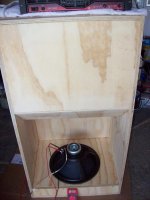
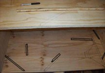
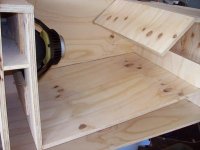
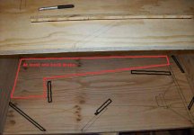
Here's some pics showing my shortened L12. I'll play around with it some more tomorrow. I didn't break in my 3015lf before measuring, and I know once done it changes things.
Right now I have a solid 102-104db from 45-95, and that's sufficient for my current need, however... that's a pretty narrow range... really need another half octave minimum.
Attachments

5.6V @ 8Ohm ?
To convert to 1W/1m readings, should we subtract 3 dB?
Thanks for sharing your progress, this is fascinating. It seems like other areas, such as ported cabinets have been done to death, but there is so much more to be done here with tapped horns!
Ben
To convert to 1W/1m readings, should we subtract 3 dB?
Thanks for sharing your progress, this is fascinating. It seems like other areas, such as ported cabinets have been done to death, but there is so much more to be done here with tapped horns!
Ben
Last edited:
High passing is important
Many equalizers offer a high pass.
My Peavey (PEAVEY Q1311 PEAVEY Q1311 ) has a 40Hz high pass @ 12 dB per octave.
I have another Equalizer(THE T.RACKS EQ 1215E THE T.RACKS EQ 2231E ) with a variable frequency high pass, but also only 12 dB per octave.
Power amplifiers now also sometimes offer high passes. E.g. Behringer offers a choice of 30Hz or 50 Hz (where 50Hz is too high for my subwoofer applications, and 30Hz is a little too low!). Does anyone know - the pdf manual does not state the dB per octave - how steep the behringer cut is?
Is it sensible or useful to combine the effect of two different high passes? (40Hz, 12 dB and 30 Hz unknown dB)
can I use the variable frequency equalizer, but start highpassing an octave higher, whilst boosting the frequencies down to 40Hz to recover the lost sound? Or will such levels of boosting sound terrible?
Ben
absolutely I will put in braces oliver. However, for 'playing' purposes, I left them out.
Wind is lower today, I got to do a 28v test, 120-122db@1m from 45-95Hz. And yes panels were vibrating and leaks were happening, so it doesn't quite line up with my 5.6v tests. I think it's time to wrap this test up and get out the glue. I was really hoping for a quick one build day, 1.5 sheet cabinet that I could use for general purpose reasons.
Wind is lower today, I got to do a 28v test, 120-122db@1m from 45-95Hz. And yes panels were vibrating and leaks were happening, so it doesn't quite line up with my 5.6v tests. I think it's time to wrap this test up and get out the glue. I was really hoping for a quick one build day, 1.5 sheet cabinet that I could use for general purpose reasons.
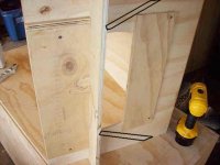
I put the 'wings' in, but it didn't make that big of a difference. Biggest difference was the small bottom/back reflector. Scott did a 11x6 opening, I did a 14x4, so I'm guessing the wider opening made the s1-s2 side reflectors less useful. (which was my guess, and why I did the wide slot in the first place)
glue tonight, paint tomorrow, install friday... these gotta go. At least I learned a little this time, instead of repeating what I've done before.
glue tonight, paint tomorrow, install friday... these gotta go. At least I learned a little this time, instead of repeating what I've done before.
- Home
- Loudspeakers
- Subwoofers
- jbell's set of four tapped horns