Hi, very nice and neat layout.Alright! Got it all wrapped up today. Flipped the switch, no magical smoke or angry pixies dancing around - set the power, JFET current and DC offset no problem-o. Loving the the Mogami 2330 - will be using this for signal in future projects for sure. This thing sounds awesome! Dude, ZenMod - you're the man! This was a fun build for sure - appreciate the help here, awesome group of people. Special thanks to ZenMod, ItsAlllnMyHead and Birdbox! Can't forget Pappa Pass too! Such a fun hobby
View attachment 1445415View attachment 1445416
I really like to build this, but am not sure if there is any chance of the SE being restock.
I think I know the answers here but wanted to check:
- the nub thing on the twister does not align with the hole cut-out, I assume thats safe to just cut off?
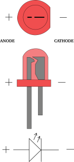
- the leds - the positive / long matches end faces inward right? EG the outer is the - / ground right?
- the way the traces look to my crap eyes shows that outer trace connecting for the leds. Each led trace seems to head to the pins of the connector so pretty sure I have it right
1. You can cut it off.
2. See below

If your Twister board looks like this (V.3), but is black... and it should...

...then the other side should look like this...

The little C (Cathode) and the flat side on the silk screen are clearly marked.
Shout if it's unclear. It's a royal pain to turn them all around if you get it incorrect.
2. See below

If your Twister board looks like this (V.3), but is black... and it should...

...then the other side should look like this...

The little C (Cathode) and the flat side on the silk screen are clearly marked.
Shout if it's unclear. It's a royal pain to turn them all around if you get it incorrect.
Last edited:
So the magic smoke stayed inside this chips 😉
Other than buying the wrong freaking fuse holder its all set. Going to send some music through it later but I need to do some wiring cleanup first!
Thanks all for the responses!
Other than buying the wrong freaking fuse holder its all set. Going to send some music through it later but I need to do some wiring cleanup first!
Thanks all for the responses!
Say, I know I've previously seen a BOM for balanced Iron Pre. Link in post #1 doesn't function, but I think I bumped into that last time. Can't remember part # for shurter unit back panel is cut for.
Russellc
Russellc
Post in thread 'Iron Pre Essentials Kits For The DIYA Store - Register Your Interest'part # for shurter unit
https://www.diyaudio.com/community/...re-register-your-interest.390509/post-7966009
In ordered the wrong fuse drawer so pay attention. I need the one for 2 fuses as both live and neutral are fused 😉
Which link? I'll see if I can fix that.Link in post #1 doesn't function,
It shows BOM for balanced may 26 23. I just sent this message somewhere, here it is again, lol
Scroll down to updates.
Russellc
Scroll down to updates.
Russellc
This is that thread! Unless I messed up and a mod moved it here. Yup, I've done the fuse drawer reorder before! So frustrating, but there it was and I missed itPost in thread 'Iron Pre Essentials Kits For The DIYA Store - Register Your Interest'
https://www.diyaudio.com/community/...re-register-your-interest.390509/post-7966009
In ordered the wrong fuse drawer so pay attention. I need the one for 2 fuses as both live and neutral are fused 😉
Hi all - first post here. Transformer questions - I have Antek 0218 which has dual R/B AC input leads. I was originally planning on terminating one set of input leads with wire nuts and utilizing just one set. I was going to switch through the black + leads to the L post of the AC input and have red - go to N post. That would seem to agree with the wiring diagram in the build guide. But I also see in the build guide that the input leads are siamesed in a red pair and black pair and that the red is switched. Do I need to siamese the input wires into bundled pairs or red-red and black-black? Does it matter whether red or black go to L or N? Doesn't seem so. Still learning, thank you.
My wiring:
Primary: Reds go to live, Blacks go to neutral
Secondary see https://www.diyaudio.com/community/...re-register-your-interest.390509/post-7974943
Because the PEM has a switch I am not using the toggle in the front. This thing will draw such a small amount of power I don't care enough to turn it off when not in-use. IF I decide to I have an overkill timer running on a microcontroller / power switch that I can just plug this in to.
If anyone wants the power controller thing I made ask - its not that complicated. Bit 'o python and some hardware.
Do I need to siamese the input wires into bundled pairs or red-red and black-black
so called dual primary xformer, where each section is 115Vac, yes, that's proper wiring for 115Vac mains
- Home
- Amplifiers
- Pass Labs
- Iron Pre Essentials Kits For The DIYA Store - Register Your Interest
