
A
ccw-cw 18.8 kohms
ccw-wip 2.16 kohms
wip-cw 16.87 kohms
B
ccw-cw 19.0 kohms
ccw-wip 2.21 kohms
wip-cw 17.09 kohms
ccw-cw 18.8 kohms
ccw-wip 2.16 kohms
wip-cw 16.87 kohms
B
ccw-cw 19.0 kohms
ccw-wip 2.21 kohms
wip-cw 17.09 kohms
now it is logical
Pot is OK
taking in account that you confirmed with buzzer that pot pins are connected to proper screw contacts as :
CCW to COM
WIP to OUT
CW to IN
now, routing to preamp pcb is, screw contact on pot pcb to preamp pcb pads:
COM to CCW
OUT to WIP
IN to CW
if that is ok, again confirmation with buzzer test, pot must be in mid position, test continuity between each pot pin and appropriate pad on preamp pcb
also, when wiring is completed, again test with buzzer between pot pins, to establish there is no shorts with pot in circuit
I connected as before:
CWR-AIN
WIPR-AOUT
CCWR-ACOM
CCWL-BCOM
WIPL-BOUT
CWL-BIN
Continuity everywhere except CCWR pad. The conductor is continuous but not the pad. I had desoldered the right side a while ago because wires were placed wrong (per IXNAY’s experience). I think they are in the right place now. Question: The traces imply a common ground between CCWR and CCWL. Is it possible to bridge to CCWL rather than try and recover my torching of the pad?
CCWL and CCWR are both GND on preamp pcb, so - yes - shorted
thin wire bridge, connecting CCWR and CCWL pads, and you're good
for future - avoid non-leaded solder, practice soldering and desoldering skills, never hurry
thin wire bridge, connecting CCWR and CCWL pads, and you're good
for future - avoid non-leaded solder, practice soldering and desoldering skills, never hurry
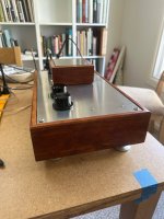
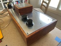
it’s alive! Thank you all who helped me across the finish line. Timkrone, Ixnay, ItsAllInMyHead, and especially Zen Mod!! So many lessons learned which I’ll summarize in another post but basically I had no continuity to the board at one lead from the volume pot. I’m going to put in the main system now and feel the zen. Thank you.
Attachments
Bonjour,
Je sais pas si il s'agit du bon fil de discussion mais dans le doute !
Sur un Iron Pre Balanced et il possible de faire 2 entrées XLR et 3 entrées UNBALANCED ? En conservant la sortie BALANCED.
J'ai un ampli en schéma SUSY de Nelson Pass que je voudrais garder en BALANCED.
Desolé pour les fautes potentiels j'utilise un traducteur.
Hello,
I don’t know if this is the right thread but in doubt!
On an Iron Pre Balanced and it is possible to make 2 XLR inputs and 3 UNBALANCED inputs? By keeping the BALANCED output.
I have a Nelson Pass SUSY amp that I would like to keep in BALANCED.
Sorry for the potential mistakes I use a translator.
Balanced Iron Pre, how to arrange any input as SE, procedure is simple:
that's it
- install small thin wire bridge on intended input pads and solder it, between pads -X and XGND, where "X" is input designation number
- mount RCA jack for that input
- wire it to corresponding input pcb pads, RCA GND to XGND and RCA hot to +X, again where "X" is input designation number
- install and solder diode DIX, again where "X" is input designation number
that's it
Merci Zen Mod c'est ce qu'il me semblait qu'il était possible de faire un mix des entrées.
Thank you Zen Mod it is what it seemed to me that it is possible to make a mix of the entries.
Thank you Zen Mod it is what it seemed to me that it is possible to make a mix of the entries.

Hi all - Back after a couple of crazy weeks. Has politics infused every single thing in life with a layer of funk? Local politics has certainly affected my work life. Anyway, the Iron Pre was the most difficult project for me to date and it was all self inflicted. An EAR 834P Phono Preamp clone was the next hardest and the full boat Aleph J was easy by comparison. I like to build my own chassis and do layout so that adds something to the challenge.
Lessons learned:
Assumptions: Now I know how volume pots work. Don't assume, know what goes to what rather than rely on the Build Guide.
Workmanship: Hum - As Zen Mod predicted I had a huge amount of hum from what was assumed to be power transformer placement. Wrong - I had installed the RCA's with the ground tab on the chassis side instead of the insulated side. Ground loop hell. Doh!!
PCB Versions: When there are multiple iterations of PCB boards, make sure you are installing off the correct version. I built up the twister board based on the wrong version and screwed up the LED's. I triple check it and still got it wrong. Thankful;ly, there are some very decent folks on this forum. Thank you TimKrone for the replacement twister pcb.
Desoldering: I screwed up at least two through-holes. I need to better learn how to desolder and practice.
Small details matter: I built the PCB's perfectly, did everthing right. The volume pot and RCA jack wiring, fairly ordinary things, were what got me.
This thing is a serious piece. The amp now sounds great and all systems are go. It is clean, transparent, and goes deeper into the music, - truly a marked difference in fidelity and musicality. Speakers are 1970 Altec Boleros and amp is an Aleph J. Sources are EAR 834P + Technics SL1700 + Schiit Modius +Tascam CD player.
Next up - Pearl 3. I am afraid of the SMD's!
Thank you all.
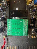
Hi IAIMH - I‘ve reviewed all the posts here and also the diagram in post #1 which is really clear … but I decided to go with a single Alps RK27 4-gang for my balanced V4 PCB‘s and am still confused how to wire that up. 😅A few things -
It's highly likely that you have your pot wired incorrectly. See post #1 for a diagram. That should fix the volume issue.
Make sure the twister board is getting power from the main board at the LED resistor. If it is, then the LEDs will light when inserted properly and the input is switched (unless you've cut some traces and/or used an improper switch).
Do A and B go to + and - respectively of board one, and C and D go to + and - of board two? Grateful if you could help out. Thanks!
Attachments

I‘ve reviewed
use A and B for one channel
use C and D for other channel
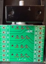
check proper routing of your alps pcb, if it is OK , use it
if not, solder wires directly to pot pins
edit: pcb as shown, need to be flipped left to right
GND Pads needs to be connected to CCW pins
Attachments
Last edited:
Hello,
I allow myself to come back to ask questions.
I’m trying to make an integrated of 'competition' and I will say and I will need to resolve a few points to really define 'my product':
-is it possible to make a BY PASS entry? for a Home Cinema for example
-I am thinking of doing the input selection command via Arduino (if I manage to make code...)
I think that as my thoughts progress, other questions may come.
Sorry to bother you with that
- Home
- Amplifiers
- Pass Labs
- Iron Pre Essentials Kits For The DIYA Store - Register Your Interest