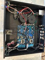


The transformer primary wiring looks strange to me. I see each transformer has a pair of black primary wires and a pair of red primary wires. I see the red wires twisted together and black wires twisted together. I see a twisted black pair clearly connected to one point on the connection block. So it looks to me that the wires from two primary windings are twisted together. Or are my eyes deceiving me? That is not the usual or best way to pair wires for noise reduction.
The wires from each primary winding should be twisted together for best noise reduction. So if each primary winding has a red and black wire, they should be twisted together.
Similarly the wires from each secondary winding should be twisted together for best noise reduction.
A tighter twist on the AC wires from the IEC jack would be beneficial too.
I don't remember it being an issue. I think I run my iron around 600-625 F. Put some flux on the wire and pre-tin your tip. The only time I saw the insulation melt was when I used a solder pot.Does the insulation hold up well to heat? Some of them melt like crazy before you have even started. OTOH, the same insulation that works well in heated conditions (Teflon) can be a real test to prep. Strips hard, but solders well.
@Ben MahThe transformer primary wiring looks strange to me. I see each transformer has a pair of black primary wires and a pair of red primary wires. I see the red wires twisted together and black wires twisted together. I see a twisted black pair clearly connected to one point on the connection block. So it looks to me that the wires from two primary windings are twisted together. Or are my eyes deceiving me? That is not the usual or best way to pair wires for noise reduction.
The wires from each primary winding should be twisted together for best noise reduction. So if each primary winding has a red and black wire, they should be twisted together.
Similarly the wires from each secondary winding should be twisted together for best noise reduction.
A tighter twist on the AC wires from the IEC jack would be beneficial too.
You mean like this?
Your sketch is incomplete as it does not show the wires connected to the primary windings.
The wires from each primary winding should be twisted together. So if a red wire and a black wire are connected to one primary winding, they should be twisted together. Then one of the wires (can be red) is connected to the AC hot and the other wire (black) is connected to the AC neutral.
That is repeated for the other primary winding and for the other transformer.
Are the wires red and black for each transformer primary?
What is the transformer? Do you have a specification sheet or is there a wire diagram on the transformer?
I just spoke with Antek and confirmed all 4 red are connected together and all 4 black wires are connected together (for 120v AC). Here's a diagram of the transformer.Your sketch is incomplete as it does not show the wires connected to the primary windings.
The wires from each primary winding should be twisted together. So if a red wire and a black wire are connected to one primary winding, they should be twisted together. Then one of the wires (can be red) is connected to the AC hot and the other wire (black) is connected to the AC neutral.
That is repeated for the other primary winding and for the other transformer.
Are the wires red and black for each transformer primary?
What is the transformer? Do you have a specification sheet or is there a wire diagram on the transformer?
Yes, reds are connected together and blacks are connected together.
However, the red/black of each primary winding should be twisted together.
The wires are then separated to make the connection at the connection block.
However, the red/black of each primary winding should be twisted together.
The wires are then separated to make the connection at the connection block.
Got it. I'm in the process of re-doing the secondaries and will do the same for the primaries. Appreciate the help.
I get it. This stuff can be confusing when some information is lost in translation. Some of the transformer suppliers do great for making a complete diagram, while others may leave out needed info (especially if you buy second hand on eBay). My brain really likes one primary and one secondary because of needing to get the windings in 'agreement' with each other.
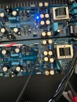
Good news. Bad news. I finished re-twisting the wires and re-adjusting P1/P2 and nulling DC offset; however, in my rush to hook everything back up, I forgot to cap the jumpers on one of the boards. Now the DC offset for JP+ swings violently up and down (JP- is steady) and the volume is through the roof. Did I ruin the cinemag and/or other parts?
Attachments
remove jumpers and recheck DC Offsets; inform here
check Rdc of autoformers; need to see same Rdc between output pins at XLR (2, 3) ref to GND
roughly 50R
not likely that you did damage Cinemags with JFet offsets, more likely that you have some fishy soldering or misplaced part
check Rdc of autoformers; need to see same Rdc between output pins at XLR (2, 3) ref to GND
roughly 50R
not likely that you did damage Cinemags with JFet offsets, more likely that you have some fishy soldering or misplaced part
Much better now. I do notice that when I change inputs, there’s a slight delay with the relays “clicking” between left and right channels.
One channel switches immediately and a second later the relay for the other channel engages. The delayed channel comes on noticeably louder, too.
I will double check the RDC on pins 2/3 to see if the left and right channels match resistance.
Should there be a delay between left and right relays?
One channel switches immediately and a second later the relay for the other channel engages. The delayed channel comes on noticeably louder, too.
I will double check the RDC on pins 2/3 to see if the left and right channels match resistance.
Should there be a delay between left and right relays?
^ Is it the left and right boards behaving differently and/or is it possibly K6? I've never noticed a difference in timing from left and right channels. However, K6 (for SE inputs) is slightly delayed (possibly due to C12?). Do you have any of your inputs set up for SE? Do the "clicks" vary when moving from SE to SE / Bal to Bal inputs or only from SE to Bal or Bal to SE?
Just tossing out an idea and my experiences across a few builds, ultimately ZM is omniknowing. 🙂
Just tossing out an idea and my experiences across a few builds, ultimately ZM is omniknowing. 🙂
as Patrick is saying ..........he's hearing K6 in action; when going from Bal in to SE in, K6 is engaging with delay; when going from SE in to Bal in, K6 is disengaging with delay
due to tolerance in caps in parallel to K6 coil, there will always be some difference in said delay between channels (K6 on one pcb, K6 on second pcb)
same as having different length of pinky on left vs. right hand, completely normal
there can't be any other delay, having physical MBB Lorlin switches
confirm that you have proper 24V-ish relay PSU operational on both channels and - if yes, just chill
Last edited:
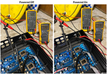
Okay. I brought it back in my lab/garage to take some measurements of RDC powered on and off for comparison. Should the resistance change between off and on?
I only have 2 inputs wired (1 balanced and 1 SE). I soldered diodes on DI2-DI5 and shorted inputs 3-5 on both boards respectively.
I will look through the thread to see how to measure for 24V relay PSU.
I only have 2 inputs wired (1 balanced and 1 SE). I soldered diodes on DI2-DI5 and shorted inputs 3-5 on both boards respectively.
I will look through the thread to see how to measure for 24V relay PSU.
Attachments
- Home
- Amplifiers
- Pass Labs
- Iron Pre Essentials Kits For The DIYA Store - Register Your Interest