OK, that's what I suspected 😉
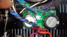
The best way to measure - use the empty holes near each 0.22R resistor - see attached. This way you measure the voltage over 2 resistors in series at once.
Measure the voltage between 1 and 1 first, then - just to check - between 2 and 2. Divide the voltage by 0.44R (as you've got 2 resistors there) - get the current. For 80mA per pair it should be 35-36mV.
Just set it at 36mV across both test points. Offset is still stable at 1mV.
It's definitely running warmer now like a proper class AB.
Last edited:
We're only a UPS truck apart. I'd like to start doing custom order chassis soon. I'm building a bunch for myself to get the processes fine tuned. They're getting easier.
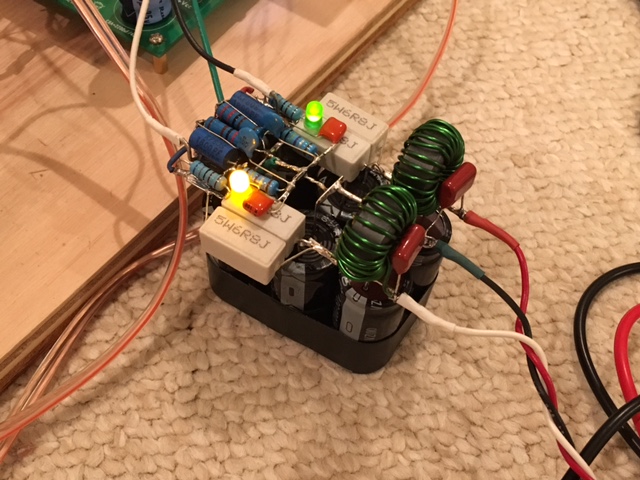
My hat out!!!The laser shop was really quick with my covers. I've got it together and powered up. Tomorrow morning I'll find my bench top again and begin testing.

I wish I lived closer to you.
I too feel the same way. Amazing job on those cases and build Jeff!.
prasi
The laser shop was really quick with my covers. I've got it together and powered up. Tomorrow morning I'll find my bench top again and begin testing.
Very cool! Short power wires and perfect match of the amp and the case.

Well - anodizing and stuff... Jeff, you are a wizard 😀
One point for further optimization I see for myself - for some later version I should make the "mirrored" PCBs - left and right, exactly as you did for a bigger amp series with non-switching OPS.
I like having no input wiring. Those connectors work great for that!Very cool! Short power wires and perfect match of the amp and the case.
Well - anodizing and stuff... Jeff, you are a wizard 😀
One point for further optimization I see for myself - for some later version I should make the "mirrored" PCBs - left and right, exactly as you did for a bigger amp series with non-switching OPS.
Jwilhelm,
Do you find that the simple VHex power supply with just diode bridge and capacitor bank is sufficient to prevent any residual hum from getting through? How much ripple do you have at the power supply when the amp is not playing music? I get 5mV on 35v rails and it is dead quiet but have a more complicated supply with CRCLC filtering scheme. Just wondering if I can get away with simple if the amp does well.
Do you find that the simple VHex power supply with just diode bridge and capacitor bank is sufficient to prevent any residual hum from getting through? How much ripple do you have at the power supply when the amp is not playing music? I get 5mV on 35v rails and it is dead quiet but have a more complicated supply with CRCLC filtering scheme. Just wondering if I can get away with simple if the amp does well.
I have simple dual supplies with dual bridge in this build with a single transformer. Valery's designs are good enough that no special supplies are needed.
When I bench tested it with a single supply, the soundstage was good, but not as wide as the Vertical NS-OPS I just finished. With the dual supplies, the soundstage is noticeably wider. This thing sounds excellent! I'll take some proper measurements this evening.
When I bench tested it with a single supply, the soundstage was good, but not as wide as the Vertical NS-OPS I just finished. With the dual supplies, the soundstage is noticeably wider. This thing sounds excellent! I'll take some proper measurements this evening.
Attachments

I have simple dual supplies with dual bridge in this build with a single transformer. Valery's designs are good enough that no special supplies are needed.
When I bench tested it with a single supply, the soundstage was good, but not as wide as the Vertical NS-OPS I just finished. With the dual supplies, the soundstage is noticeably wider. This thing sounds excellent! I'll take some proper measurements this evening.
What is the advantage of dual bridge rectifier? What is the ripple from your PSU?
I will look into making dual PSU's as I was able to make mine really compact with point-to-point.
This amp does indeed sound really nice - the distortion is very low and dynamic headroom is great.
Last edited:
Jeff,
So you are using a simple capacitor filter. what value? I am used to over the top crc capacitor banks. going simpler would save a lot of cash.
Thanks,
E
So you are using a simple capacitor filter. what value? I am used to over the top crc capacitor banks. going simpler would save a lot of cash.
Thanks,
E
I go by Slone's guidelines. 10000uF for every 100W of output power.
That sounds like a reasonable value. I have 28,200uF (6x4700uF) in the above PSU so I guess I am good to use it for stereo even?
Yes, separate caps bank (and rectifier) for each channel is recommended.
Single transformer of appropriate VA is ok, but all the other things have to be individual for each channel for the best listening experience 😎
Single transformer of appropriate VA is ok, but all the other things have to be individual for each channel for the best listening experience 😎
Dual bridges and dual supplies eliminate the possibility of crosstalk which leads to a narrower soundstage. I'm getting 53mV of supply ripple right at the power inlet connection of the amp module. Not really quiet at all, but a non issue with a good amp design. I haven't measured noise on the output yet, but I can't hear anything with my ear to the tweeter.
Last edited:
10,000 per rail or total per channel?
I would do it per rail. With a little bit of overkill, I use 3 x 6800uF caps per rail,
per channel. So, 6 caps per channel bank, 12 in total (roughly up to 120W of output power per channel, but in practical home listening - much less most of the time of course).
Dual bridges and dual supplies eliminate the possibility of crosstalk which leads to a narrower soundstage. I'm getting 53mV of supply ripple right at the power inlet connection of the amp module. Not really quiet at all, but a non issue with a good amp design. I haven't measured noise on the output yet, but I cant hear anything with my ear to the tweeter.
Ok, I will go with separate PSU's - they are not hard to make and I can see the point with crosstalk as the main OPS of each channel is directly connected and one side can affect the other side with such a low impedance connection.
I was at 60mV with my earlier PSU and feel that there is a noticable difference with this latest one at 5mV.
- Home
- Amplifiers
- Solid State
- IRFP240/9240 Amplifier (simulated on TINA)