
vHEX first sound
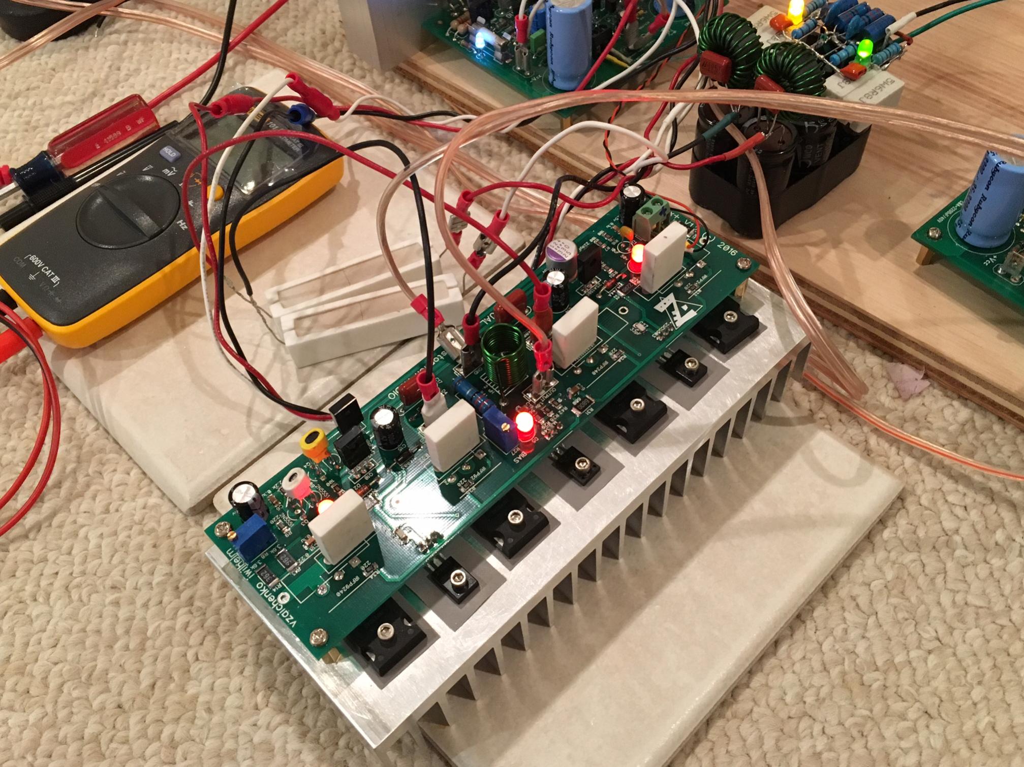
I received the heatsinks today (heatsinksusa.com) - these are really thick and heavy. A great value at $2.63/inch (3 inch long extrusion). After some drilling and tapping, I hooked it up with some 10R safety resistors. It fired right up. I set bias to recommended 80mA and offset is 0mV super stable.
It sounds very very nice. It's late at night so I can't crank it up but no audible sign of distortion. I am using it with a 35v PSU at the moment but will build a 49v PSU soon.
Attachments

I received the heatsinks today (heatsinksusa.com) - these are really thick and heavy. A great value at $2.63/inch (3 inch long extrusion). After some drilling and tapping, I hooked it up with some 10R safety resistors. It fired right up. I set bias to recommended 80mA and offset is 0mV super stable.
It sounds very very nice. It's late at night so I can't crank it up but no audible sign of distortion. I am using it with a 35v PSU at the moment but will build a 49v PSU soon.
Congratulations! Welcome to VHex club 😀
Great job and excellent build.
At 80mA, and with such a big heatsink, this amp runs very cool (barely warm) at normal listening levels and 35v rails. It will be interesting to use it on 49v PSU and crank up the volume. Perhaps a stress test on a dummy load to measure max power will get some heat out of it?
It will definitely heat up at high power (even 50W during 15-30 minutes will warm it up considerably). However, at normal room listening levels it will be just moderately warm.
It was very late last night and I now realize the bias was set thinking my old ways of a single transistor output stage. I set 80mA based on 0.80v across the 10R external resistor so that is global idle current (which is probably less than 20mA since there are 4 transistors?). I probably need to take measurement across 0.22R resistor to get actual bias current. But that is one transistor - do you have recommend test point for voltage probe to set bias for both transistors or do one by one and add up?
OK, that's what I suspected 😉
The best way to measure - use the empty holes near each 0.22R resistor - see attached. This way you measure the voltage over 2 resistors in series at once.
Measure the voltage between 1 and 1 first, then - just to check - between 2 and 2. Divide the voltage by 0.44R (as you've got 2 resistors there) - get the current. For 80mA per pair it should be 35-36mV.
Attachments

OK, that's what I suspected 😉
The best way to measure - use the empty holes near each 0.22R resistor - see attached. This way you measure the voltage over 2 resistors in series at once.
Measure the voltage between 1 and 1 first, then - just to check - between 2 and 2. Divide the voltage by 0.44R (as you've got 2 resistors there) - get the current. For 80mA per pair it should be 35-36mV.
Ok, thanks - will do that tonight. I suspected those empty holes would come in handy just exactly for this purpose. I should have known sooner but this was my first use of such a large heatsink so kept thinking maybe it was drawing heat away better.
Ok, thanks - will do that tonight. I suspected those empty holes would come in handy just exactly for this purpose. I should have known sooner but this was my first use of such a large heatsink so kept thinking maybe it was drawing heat away better.
That's fine, you just ran it at roughly half the idle current. But even at nominal one the heatsinks will be just moderately warm. You'got very good ones!
Yes, I am very impressed with the quality of the heatsinks from heatsinkusa.com. These are the thickest, heaviest pieces of finned aluminum extrusions I have seen for such a low price. I highly recommend them to anyone building DIY amps. Thanks to Jwilhelm for the tip on this as a source of good heatsinks.
Even with increased bias, I think they will still be relatively cool-running.
Even with increased bias, I think they will still be relatively cool-running.
Yes, I am very impressed with the quality of the heatsinks from heatsinkusa.com. These are the thickest, heaviest pieces of finned aluminum extrusions I have seen for such a low price. I highly recommend them to anyone building DIY amps. Thanks to Jwilhelm for the tip on this as a source of good heatsinks.
Even with increased bias, I think they will still be relatively cool-running.
I like their products too. It would be nice if the base was a little thicker though. .300" isn't a lot of depth to drill and tap, and drilling through looks terrible.
Mine stayed fairly cool for the week I had it running on my test bench. Hopefully the laser shop has my covers done for the weekend, so I can assemble this and give it a proper test/audition. I'm quite happy with the sound so far. You wouldn't know it's a little 90W amp if you didn't see it.
Agreed - but I can't complain for $2.63/inch. 🙂I like their products too. It would be nice if the base was a little thicker though. .300" isn't a lot of depth to drill and tap, and drilling through looks terrible.
It's especially bad if the hole lands at the junction of a fin - the drill bit wants to wander and I broke a bit this way (lucky enough to be able to punch it out and remove bit). Subsequently I avoided drilling through so taps are rather shallow. With a bottoming tap, it should help though.
I wish there was an economical solution for a case. Seems like what you are doing with custom panels bolted on makes sense.
I used to use 6-32 standoffs from PCs. The thread is .250" long on them, so it was pretty much necessary to drill through. I've switched to M3 standoffs, which are much shorter.
You can do an economical chassis with sheet metal and some small bar stock or angle iron for the joints. That's how most DIY chassis are done. Check out the ones in the DIYAudio store. That's how they are done. I have a couple milling machines, so I like to play with billet for mine.
You can do an economical chassis with sheet metal and some small bar stock or angle iron for the joints. That's how most DIY chassis are done. Check out the ones in the DIYAudio store. That's how they are done. I have a couple milling machines, so I like to play with billet for mine.
I use 4-40 tap so similar to M3. Probably should get an M3 drill and tap as most of my stand off screws and hardware are now M3. I will give the sheet metal and angle stock a look. I did see the diya store boxes.
It's Alive!
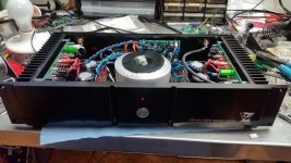
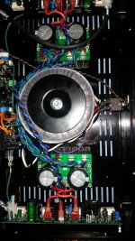
The laser shop was really quick with my covers. I've got it together and powered up. Tomorrow morning I'll find my bench top again and begin testing.
The laser shop was really quick with my covers. I've got it together and powered up. Tomorrow morning I'll find my bench top again and begin testing.
Attachments


- Home
- Amplifiers
- Solid State
- IRFP240/9240 Amplifier (simulated on TINA)