Q19 is configured as a current source. Current that flows into Q19 emiter is practically the same that comes out from Q19 collector and further flowing through Q14. Base currents of Q19 and Q13 are about 200x lower (beta of transistors) so we can ignore their contribution.
70C on heatsinks is not surprising. It is 30C degree above the ambient temp. So the thermal resistance of the heatsink is 30C/0.77W ~ 40K/W. I would say not unrealistic for such a tiny hs.
70C on heatsinks is not surprising. It is 30C degree above the ambient temp. So the thermal resistance of the heatsink is 30C/0.77W ~ 40K/W. I would say not unrealistic for such a tiny hs.
BTW interesting design. Similar to something I've done recently. I tought my design was original but obviously some folks have already came to the same idea. However I'm running it in A class. In my opinion this design (Square Law Push Pull) is at it's best when biased in A class.
Are you satisfied with it? How does it sound?
Are you satisfied with it? How does it sound?
That doesn't prove much.If you had really good insulators(keratherm) and the mosfets were clamped properly then touching the heatsink would be a good test.A keyring and whatever else you have there is not the best.I can touch the heatsinks for about 5 seconds before recoil. No screams 🙂
Already got the feeling the heat issue was discussed partly elsewhere. The device has more than 1 design imperfection as heat is generated very nearby too.
https://www.diyaudio.com/community/...servo-power-supply.386573/page-4#post-7068539
It has the regulators connected to the main power rails thereby dropping much voltage converted to useless heat. If I recall correctly the device drops 50V to 15 V and such times 4 while actually having a separate +/- 15V PSU for the phono stage*............................... A trainwreck of a design but it can partly be solved by placing an external +/- 15V 100 mA miniature PSU for the DC servo and current sense opamps which is a simple and adequate solution. The other possibility was to connect the DC servo and current sensing opamps to the phono PSU as it has LM317/LM337 that won't blink an eye with extra 20 to 40 mA load. There the voltage drop is 25 to 15V times 4. Environment less hot = IRF9610 less hot.
A self made aluminium bracket connecting the IRF to the main heatsink with an M3 bolt is also possible. The IRF needs surface for getting rid of the heat and should of course itself be bolted to the bracket/heatsink for optimal heat transfer.
*Schematic of the phono board and its PSU is in the other thread.
This contraption is a good example of built in design imperfections. It maybe goes too far to speak of planned obsolescence but its close to it.
This thread is a good example of a few threads about generic items that are in fact subjects of a very specific device. Why would that be? It causes time loss for others and does not present the whole picture.
Last edited:
Yes, I think I uploaded photos of the mounted THT resistors in another post however - Done 🙂 The resistors are quite hot and mounted next to the output device heatsinks. The first thing I noticed was dc offset in both channels is more stable after heating up - I was measuring random 5mV spikes in the right channel. I reopened this thread because I was able to measure voltage across R26 and have been curious about how well the IRF9610 heatsinks are working given a known power usage.Already got the feeling the heat issue was discussed partly elsewhere. The device has more than 1 design imperfection as heat is generated very nearby too.
https://www.diyaudio.com/community/...servo-power-supply.386573/page-4#post-7068539
It has the regulators connected to the main power rails thereby dropping much voltage converted to useless heat. If I recall correctly the device drops 50V to 15 V and such times 4 while actually having a separate +/- 15V PSU for the phono stage*............................... A trainwreck of a design but it can partly be solved by placing an external +/- 15V 100 mA miniature PSU for the DC servo and current sense opamps which is a simple and adequate solution. The other possibility was to connect the DC servo and current sensing opamps to the phono PSU as it has LM317/LM337 that won't blink an eye with extra 20 to 40 mA load. There the voltage drop is 25 to 15V times 4. Environment less hot = IRF9610 less hot.
A self made aluminium bracket connecting the IRF to the main heatsink with an M3 bolt is also possible. The IRF needs surface for getting rid of the heat and should of course itself be bolted to the bracket/heatsink for optimal heat transfer.
*Schematic of the phono board and its PSU is in the other thread.
This contraption is a good example of built in design imperfections. It maybe goes too far to speak of planned obsolescence but its close to it.
This thread is a good example of a few threads about generic items that are in fact subjects of a very specific device. Why would that be? It causes time loss for others and does not present the whole picture.
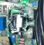
I've also added better heatsinks to the IRF9610s. I removed the top and bottom of an 8oz aluminum can, folded 4 times and then used pliers to make fin shapes. This adds about 7-8 grams of aluminum to the installed heatsink. I think it is a solid contraption with the heatsink clips.
Attachments

Last edited:
Thanks for the explanation regarding the current! I am pretty happy with the amp, and proud I was able to repair it. How can you run in class A? I've been curious about how to calculate when the amp will switch from class A to class B. The Destiny was heavily based on the designer of the Creek Audio 5350SE, Alex Nikitin aka x-pro.BTW interesting design. Similar to something I've done recently. I tought my design was original but obviously some folks have already came to the same idea. However I'm running it in A class. In my opinion this design (Square Law Push Pull) is at it's best when biased in A class.
Are you satisfied with it? How does it sound?
Last edited:
Yes now remembering as well. I think there was too much uncertainty about whether or not using another psu such as the phono board would introduce issues during a fault condition. I don’t know enough about the design to make that big of a change.Yes, I think I uploaded photos of the mounted THT resistors in another post however - Done 🙂 The resistors are quite hot and mounted next to the output device heatsinks. The first thing I noticed was dc offset in both channels is more stable after heating up - I was measuring random 5mV spikes in the right channel. I reopened this thread because I was able to measure voltage across R26 and have been curious about how well the IRF9610 heatsinks are working given a known power usage.
I've also added better heatsinks to the IRF9610s. I removed the top and bottom of an 8oz aluminum can, folded 4 times and then used pliers to make fin shapes. This adds about 7-8 grams of aluminum to the installed heatsink. I think it is a solid contraption with the heatsink clips.
I don't recommend modifying that amp. Better start building a new one if you really crave for adventure.
My amp use +/- 24V supply and is A class up to about 16W. Low supply voltage makes possible to have high bias current (about 0.7A) without destroying the output MOSFETs. It's hard to control bias current without source resistors and that prevents me from having even higher bias current.
With standard push-pull A class, pure A class power (roughly) is 2 * Iq * Iq * Rl where Iq is the bias current, Rl is the loudspeaker impedance. This means every class AB amp has some small 'pure A class' range.
With 'Square Law push-pull' output stage like in this amp, pure A class is 8 * Iq * Iq * Rl. That means 4x more than the standard class A for the same Iq.
Last edited:

Wow, can you send a photo of your amp? I guess the only modification outside of improving the thermal management is replacing HUF76639P3s (no longer available) with IRL2910s. These have different Vgs(th) values according to the datasheets: 1-3V and 1-2V, respectively. Can you tell me if that can cause an issue? I've measured Vgs at 2 volts on the IRL2910s.I don't recommend modifying that amp. Better start building a new one if you really crave for adventure.
My amp use +/- 24V supply and is A class up to about 16W. Low supply voltage makes possible to have high bias current (about 0.7A) without destroying the output MOSFETs. It's hard to control bias current without source resistors and that prevents me from having even higher bias current.
With standard push-pull A class, pure A class power (roughly) is 2 * Iq * Iq * Rl where Iq is the bias current, Rl is the loudspeaker impedance. This means every class AB amp has some small 'pure A class' range.
With 'Square Law push-pull' output stage like in this amp, pure A class is 8 * Iq * Iq * Rl. That means 4x more than the standard class A for the same Iq.
My bias current is ~70mA. Thanks for the equation. That would put class A on my amp up to 230mW, RI = 6 Ohms.
Last edited:
I already replaced the HUFs with IRL9610s. I bought the amp for parts and if I recall one channel had bad MOSFETs. The IRL9610s seem to be working fine after 1 year but I’ve always wondered if or how their lower Vgs Th is an issue. I read somewhere that there a relationship between Vgs and running in class B. However there really doesn’t seem to be a better alternate than rhe IRL2910s, and I am reluctant to replace those because it does sound great. As for sound characteristics I would say it is very clean and slightly warm. Plenty of depth in bass response. But sometimes treble can be a little harsh.Did you already replace HUF76639P3s with IRL2910s or you just consider it?
Last edited:
In this particular amp it's crucial that Vgs(th) of Q0 is greater than Vgs(th) of Q15 for at least 1V. You should check actual values.
QO Vgs =3.4 volts and Q15 Vgs = 2 volts. Sounds like all is clear. Thanks for the help !In this particular amp it's crucial that Vgs(th) of Q0 is greater than Vgs(th) of Q15 for at least 1V. You should check actual values.
Last edited:
Previously discussed current flowing through Q14 splits in two. One part flows through Q0 the other through Q12. The sum of two branches should equal the Q14 current. 1V / R26 = Vgsq0 / R22 + Vgsq12 / R24 that is 1/63 = Vgsq0/240 + Vgsq12/240. You can check that just for curiosity.
Q0 controls Q15 by changing Vgsq15. When Vgsq15 rise, Vdsq0 decrease for the same amount. That's why Vgsq0 has to be higher than Vgsq15 because that leaves some headroom for Vdsq0 to swing.
Q0 controls Q15 by changing Vgsq15. When Vgsq15 rise, Vdsq0 decrease for the same amount. That's why Vgsq0 has to be higher than Vgsq15 because that leaves some headroom for Vdsq0 to swing.
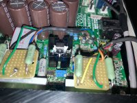
Here is the final solution to the heat management issues. I added a duplicate heatsink to the IRF9610s, and mounted those with a proper 7mm heatsink clip:
https://www.mouser.com/ProductDetail/532-CLP212SG
https://www.digikey.com/en/products...sion-of-boyd-corporation/574502B00000G/240992
Hopefully this preventative maintenance will add longevity to the amp. I also found a speaker ground connection issues at the MOLEX PCB connectors, probably caused by myself from reconnection wear and tear. After the amp warmed up there was a noticeable channel imbalance sometimes. This was verified by measuring the AC voltage (80mV L vs 60mV R - that is 2.5dB) at the speakers from a 120 Hz sine wave source. After soldering the speaker ground wires to the PCB the channel unbalance is less than 1mV. I've uploaded a photo the final modifications. Thanks again for the help and feedback.
Attachments
Last edited:
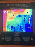
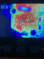
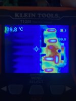
It turns out my local tool library has a thermal imager… 🙂 FWIW, the proof is in the pudding…
Unfortunately, I do not have readings before replacing and moving the power resistors to a few mm under the lid, and adding another heatsink to the IRF9610s.
Measurements were taken after warming the amp up for 2 hours with the lid on.
Room temperature - 25C
Input board PCB temperature - 35C
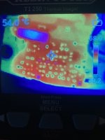
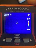
L and R Main heatsink (for IRL2910s) temperature - 40C
L and R Power Amplifier Section taken at the input stage - 55C. I took multiple readings outside of hot spots and can conclude the ambient temperature of the PAS is closer 50C. Readings drop to 40C near the volume control far away from heat sources.
DC Servo IC U1/101 (TL074CDR) - 60C
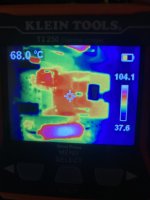
L and R heatsinks for IRF9610 temperature - 70C
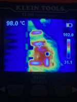
Power supply resistors (R38/39/8/9) mounted a few mm under the lid - 100C
It appears there is not much wiggle room especially at much warmer room temperatures around 30-40C.
Is a 50C ambient temperature expected for Class AB amps? Otherwise then yes it’s a train wreck waiting to happen, lol. Will definitely look into placing or installing two quiet fans.
Unfortunately, I do not have readings before replacing and moving the power resistors to a few mm under the lid, and adding another heatsink to the IRF9610s.
Measurements were taken after warming the amp up for 2 hours with the lid on.
Room temperature - 25C
Input board PCB temperature - 35C
L and R Main heatsink (for IRL2910s) temperature - 40C
L and R Power Amplifier Section taken at the input stage - 55C. I took multiple readings outside of hot spots and can conclude the ambient temperature of the PAS is closer 50C. Readings drop to 40C near the volume control far away from heat sources.
DC Servo IC U1/101 (TL074CDR) - 60C
L and R heatsinks for IRF9610 temperature - 70C
Power supply resistors (R38/39/8/9) mounted a few mm under the lid - 100C
It appears there is not much wiggle room especially at much warmer room temperatures around 30-40C.
Is a 50C ambient temperature expected for Class AB amps? Otherwise then yes it’s a train wreck waiting to happen, lol. Will definitely look into placing or installing two quiet fans.
Attachments
-
 01CEE8B7-5A8F-4505-81D0-E67570AA3AC8.jpeg519.2 KB · Views: 82
 -
 92A5A63A-688B-4849-9A0C-614CF27633E0.jpeg419.5 KB · Views: 74
 -
 417A3868-308C-4DD7-A6D8-985CEC241DB2.jpeg432.1 KB · Views: 67
 -
 ADDD8B35-7895-4D29-BBBE-25A0C8CC97EA.jpeg335.5 KB · Views: 72
 -
 6E2D0F02-BAFF-4543-889A-FA9FD84305BC.jpeg258.7 KB · Views: 73
 -
 09E3A39D-345D-4AAE-8F7F-CA864C156A02.jpeg329.9 KB · Views: 80
 -
 A35AE2D4-85F0-4221-A178-AE018CB768D3.jpeg323.7 KB · Views: 81
 -
 C4816A0F-58DB-4233-BB82-56B20BB5A64D.jpeg249.6 KB · Views: 66
Last edited:
Fans are a "solution" that brings problems (not even for free) and they're simply a plain nuisance in audio so they are not a solution but a bandaid.
As explained earlier in post #44: please think of solving the issues at the root. Take away the cause and you'll need no bandaid.
The main issue is 4 resistors that drop 50V to 15V at a certain current. Even after replacement and slight improvement they become 100 degrees Celsius effectively heating up the device internally like a built in oven. This means the solution is not adequate. Assuming a current of only 20 mA you have (50 - 15) x 0.02 and this times 4. So there is at least 3W of power converted to heat! It would not surprise me if it is double that value. This is a plain design error. Taking away the voltage dropping times 4 will solve that issue once and for all.
After lower ambient temperature in the device is realized remeasuring the IRFs will tell if further work is needed. Like it is now you have class A temperatures in a class AB amplifier and that at the wrong spots. All the fiddling around eventually will lead to the demise of this device, either because of too much reworking or because of too much heat for a too long time.
Choose the third way!
Last edited:
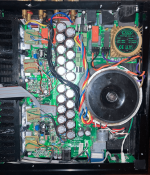
If you look carefully you'll notice a 2 x 7V toroid in the device. Now imagine a 15 Euro costing 5VA 2 x 15V Talema 70023K mini toroid upside down on top of that 2 x 7V toroid preferably with a small PCB to make wiring easier and safer. Check clearance between the new toroid and the casings cover and use plastic sheet in any case!! You'll need 30 mm at least between the 2 x 7V toroid and cover.
Measuring the current of the 2 channels combined beforehand is advisable though. Recalculate the power resistors to there Zener diodes and/or combine with new rectifiers, filter caps and regulators 7815/7915.
Solved!
Measuring the current of the 2 channels combined beforehand is advisable though. Recalculate the power resistors to there Zener diodes and/or combine with new rectifiers, filter caps and regulators 7815/7915.
Solved!
Last edited:
Yes I know about the 2x7 transformer. I see that the power resistors although directly beneath the 3mm aluminum vented lid also cause a broiler in the oven effect. Thank you for the feedback and recommendations. There are 4 power resistors per channel. 2 (R38/39) are in the the DC Servo and Current Sense power supply. How about using 15 VDC from the analog power supply in the input board to replace R38/39? I don’t think this method has been discussed. And I never use the amp in Active mode. At least that would cut half of the heat out. The other 2 (R8/9) seem more critical to the power amp circuit. Curious, can you provide a source eg a study or established industry standard for what the ideal chassis and PCB temperatures are for class AB amps? I’ve looked to no avail.
Last edited:
1. The subject of post #58 was adding a second toroid on top of it upside down.
2. Your phono board has a very healthy +/-15V by LM317/337 that don't mind 50 mA extra. You could reread all the info again in the other thread as it was already advised/discussed. It is very odd that they did not use that +/-15V but I guess that the device was not sold standard with the phono boards which would explain it.
3. The 2 x 7V toroid could be replaced for 2 x 15V one that also will feed the opamps but it would require more serious surgery and possible challenges as Vstandby will be way higher. I leave it to you to examine that possibility. I think it is too difficult and will create new heat issues so I did not look further.
Both ideas 1 and 2 have slight drawbacks which I am sure you'll see but a few minutes are enough to find out what is most easy to implement.
No studies and academic blah blah by me, I just solve practical issues. A temperature of 50 degrees in the device, 70 degrees semis and 100 degrees resistors simply are intolerable if one wants a device to keep working. It is also a waste of energy and it makes it impossible to have a device on top of this amplifier.
Last edited:
- Home
- Amplifiers
- Solid State
- IRF9610 Heatsink Measures 70-80 Celsius: Is this too hot?